
W
Wyatt ObrienJul 31, 2025
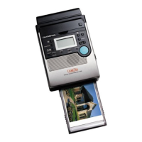
Why are both the print result and monitor display abnormal on my Olympus Printer?
- KKevin PerezJul 31, 2025
If both the print result and the monitor display are showing abnormal output, it indicates a trouble in the input block of the Olympus Printer.