2-2
OEP-3 V1 (UC)
2-2. Removal and Installation of Cabinet
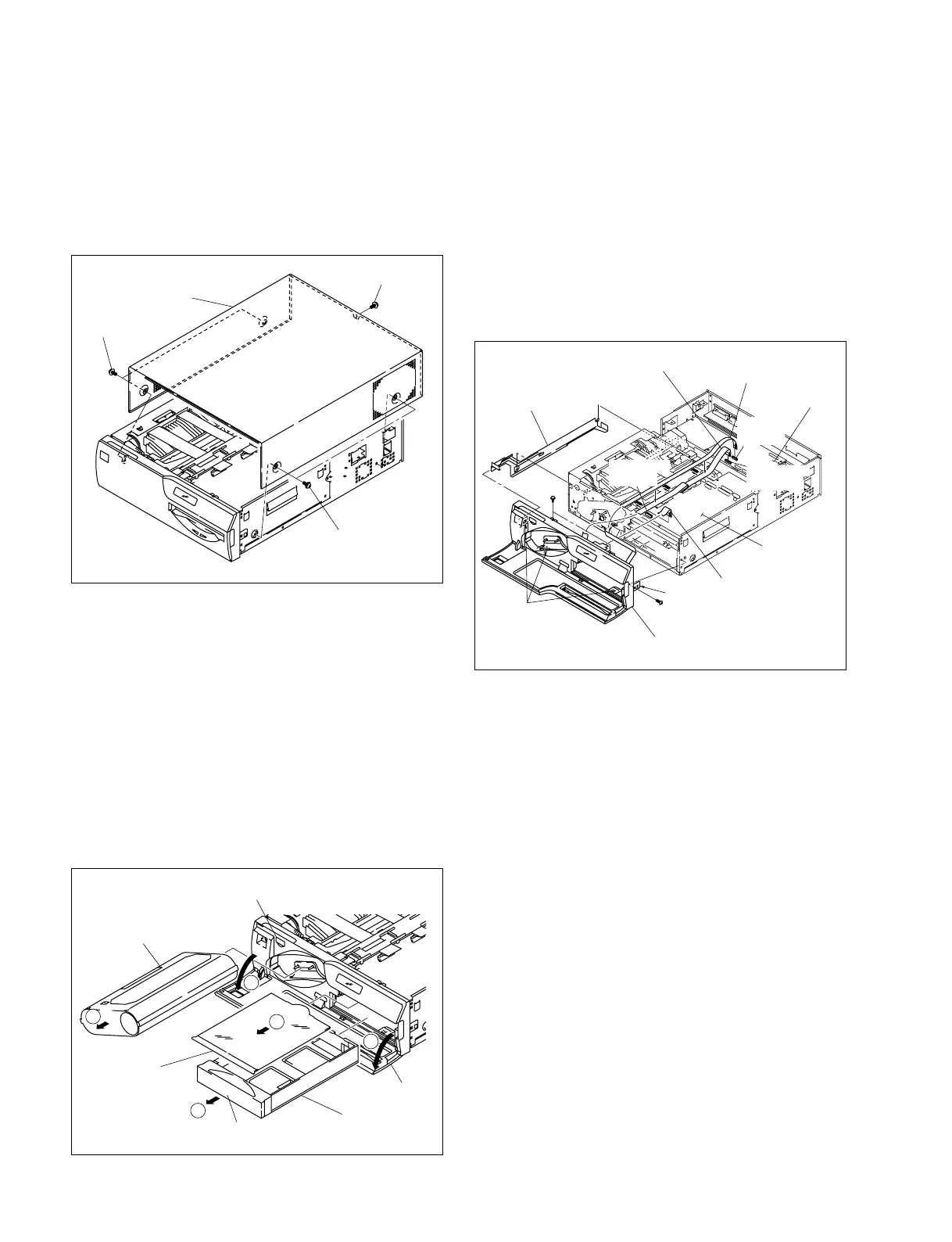
2-2-1. Top Cover
1. Remove the M3 case screws, then remove the top
cover.
2-2-2. Front Panel Assembly
1. Remove the top cover. (Refer to Section 2-2-1.)
2. Open the front door in the direction indicated by arrow
1.
3. Press the EJECT button and take out the cartridge in
the direction indicated by arrow 2.
4. Press the PUSH portion of the paper feed tray and take
out the tray in the direction indicated by arrow 3.
5. Take out the delivery tray in the direction indicated by
arrow 4.
Top cover
M3 case screw
M3 case screw
M3 case screw
PRT-13 board
SY-282 board
PSW
3x6
Hooks
Hook
BVTT 3x6
Front panel assembly
Power switch rod
Flexible flat cable (14-pin)
Flexible printed
wiring board (16-pin)
Flexible flat cable (12-pin)
Connector
(CN204)
Connector
(CN205)
Connector
(CN502)
PUSH
Delivery tray
Paper feed tray
PUSH portion
Front door
Cartridge
EJECT button
2
1
3
4
1
6. Remove the two screws (PSW 3 x 6) and one screw
(BVTT 3 x 6).
7. Disconnect the flexible printed wiring board from the
connector (CN502) on the PRT-13 board.
8. Remove the four hooks, then remove the front panel
assembly.
9. Remove the VPR-63 board. (Refer to Section 2-3-1.)
10. Disconnect the two flexible flat cables from the
connectors (CN204 and CN205) on the SY-282 board.
11. Remove the power switch rod.
12. Install the front panel assembly in the reverse order of
steps 1 to 11.