4-21
OEP-3 V1 (UC)
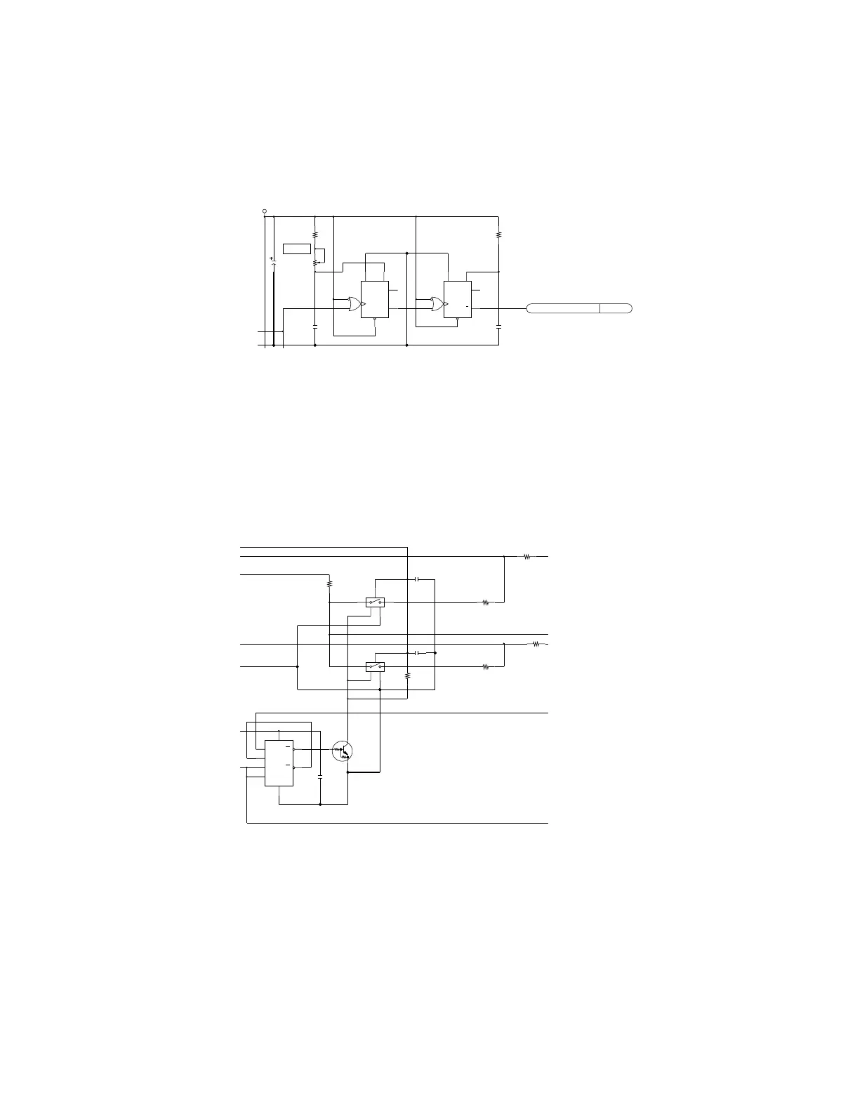
(5) HD generation circuit
The HD signal output from pin 37 of IC203 is adjusted to the proper phase and pulse width by IC207
(monostable multivibrator) and sent to the frame memory block as an HD (horizontal sync) signal for
fetching memory. AFC (Automatic Frequency Control) processing is performed for this HD signal.
(6) Demodulation axis correction circuit
Since, in a television circuit (IC203) for the consumer, the demodulation axis is not orthogonal for
NTSC, a matrix circuit (R243 to R251) is inserted into an RGB signal line so as to correct the
demodulation axis to an orthogonal axis. For PAL, the demodulation axis is orthogonal.
Demodulation is not related when an RGB signal is selected. In this case, therefore, the matrix circuit
must be turned off. The matrix circuit is switched to ON or OFF by IC205 and IC206.
Fig. 1-5 Demodulation Axis Correction Circuit
H POSI
A+5V
C261
47uF
6.3V
C263
0.001uF
RV201
2.2k
R241
3.9k
R246
6.8k
C268
0.001uF
010-B1
AFC_HD
(
2/3
)
IC207
MC74HC4538AFEL
(
1/3
)
IC207
MC74HC4538AFEL
3
2
1
15
C
14
CR
10
Q
9
Q
13
RD
12
11
1
C
2
CR
6
Q
7
Q
3
RD
4
5
R244
10k
C265
0.1uF
Q206
DTC124EKA-T146
C267
0.1uF
C266
0.1uF
R251
470
R249
4.7k
IC204
TC7W00F
(
TE12R
)
R250
470
R243
470
IC206
TC7S66F
(
TE85R
)
R248
2.2k
IC205
TC7S66F
(
TE85R
)
6
2B
5
2A
8
VCC 7
1Y
3
2Y
4
GND
2
1B
1
1A
5
43
GND
21
5
43
GND
21
 Loading...