80
Installation and Adjustment
Connections
To enable printing, video equipment to act as an input signal source, and a video
monitor to display images or menus must be connected.
The following diagrams illustrate how to make the input, output and remote control
connections. Use this as a guide when connecting the required signals to and from
the equipment to be used for printing.
Notes
• Turn off the power of each device before attempting to make any connections.
• Connect the AC power cord last.
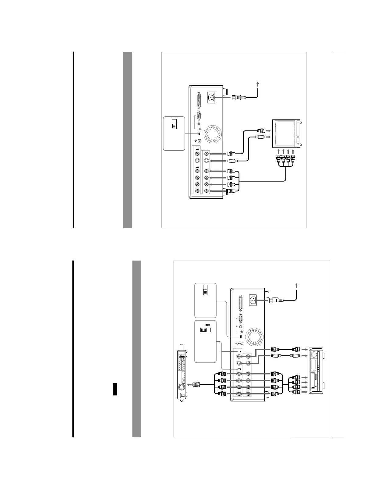
Making Connections for Capturing Video Images
Connect the video equipment providing the video images to be printed.
Connect the video equipment which will be used in actual printing, using the
following diagram as a guide.
Before connecting the video equipment, see
“Important safeguards/notices for use
in the medical environments
” on page 2.
to RGB output connectors
to S-VIDEO
output
connector
to composite video
output connector
Video system center
to S-
VIDEO
INPUT
to RGB/SYNC INPUT
to VIDEO INPUT to AC IN
AC power cord
(supplied)
to wall outlet
Connecting cable
(with DIN 4-pin
connectors)
75-ohm coaxial cable with
the BNC connectors
NTSC PAL
ON
OFF
75-ohm coaxial cable with
the BNC connectors
to RGB/SYNC INPUT
MD-445 SCV cable
NTSC/PAL selector
a)
75-ohm termination
switch
b)
Video equipment
to RGB output connectors
81
Installation and Adjustment
a) Set the NTSC/PAL selector to your TV system. To switch the TV system, turn the power off
once, then change the setting. If you change the setting with the power on, this mode will not be
switched.
To use the OEP-3 in PAL mode, contact your Olympus representative or the nearest Olympus
service center. The OEP-3 remains as is even if the NTSC/PAL selector is set to PAL.
b) Two kinds of 75-ohm termination switches are provided; one is for the RGB input and the other is
for the composite video signal. Normally set this switch to ON. Set it to OFF if the level of the
input signal drops because the signal is divided to additional video equipment other than the
printer.
Making Connections for Viewing Images to be Printed
Connect a video monitor to view stored images and to check those to be printed.
Connect the required video monitor which will be used in actual printing, using the
following diagram as a guide.
Before connecting the video equipment, see
“Important safeguards/notices for use
in the medical environments
” on page 2.
to S-VIDEO
OUTPUT
to VIDEO OUTPUT
to RGB/SYNC OUTPUT
b)
to S-VIDEO
input
connector
to composite
video input
connector
to RGB input
connectors
Video monitor
to AC IN
AC power cord
(supplied)
to wall outlet
75-ohm coaxial
cable with BNC
connectors
Connecting cable (with
DIN 4-pin connectors)
75-ohm coaxial
cable with BNC
connectors
NTSC PAL
a) Set the NTSC/PAL selector to your TV system. To switch the TV system, turn the power off
once, then change the setting. If you change the setting with the power on, this mode will not be
switched.
To use the OEP-3 in PAL mode, contact your Olympus representative or the nearest Olympus
service center. The OEP-3 remains as is even if the NTSC/PAL selector is set to PAL.
b) See “When connecting the video monitor to the RGB SYNC OUTPUT connectors
” on the next
page.
NTSC/PAL selector
a)