CAP.5 FUNZIONAMENTOEUSO
Icomandiattraversoiqualisiutilizzailsolle
-
vatoresono:
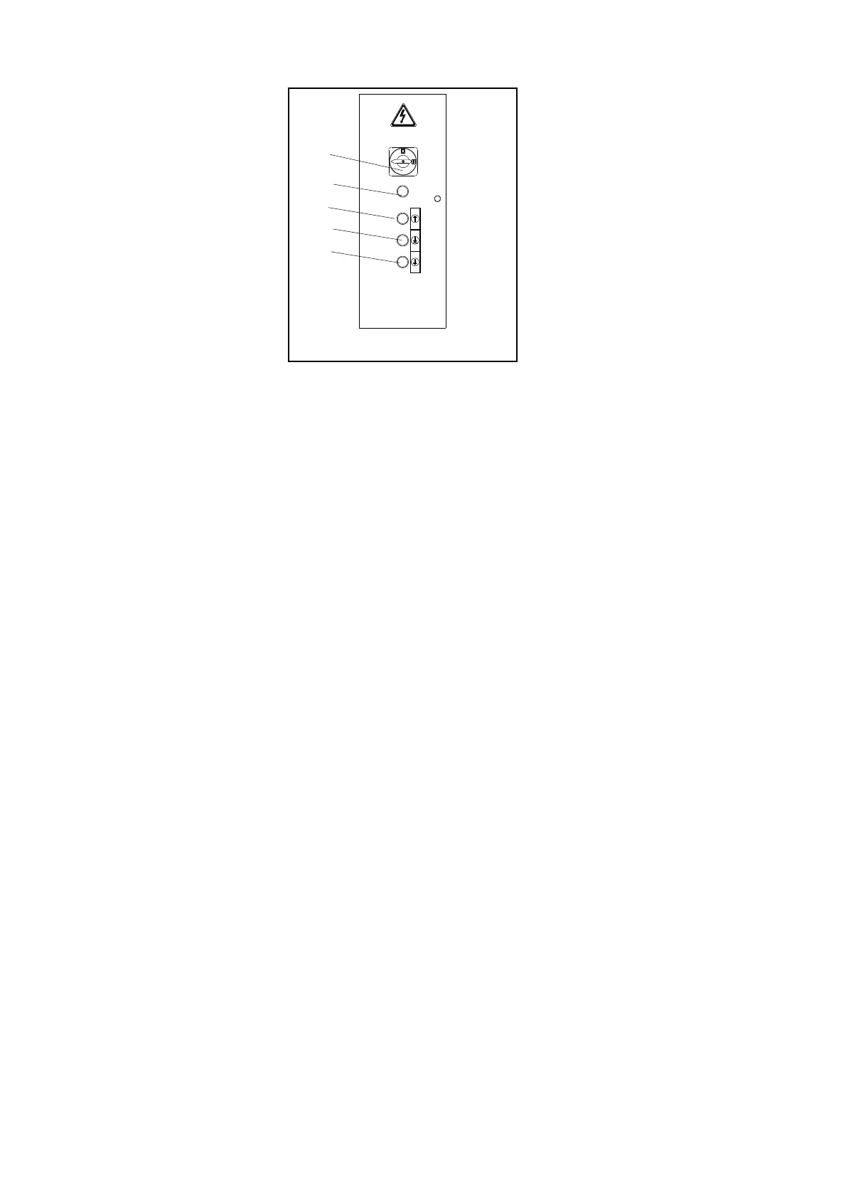
INTERRUTTOREGENERALE(QSFig.59)
POSIZIONE0:ilsollevatorenonéintensio
-
ne,épossibilel’accessoall’internodelqua
-
dro;éaltresìpossibilelucchettarel’interruttore
perimpedirel’usodelsolllevatore.
POSIZIONE1:dàtensionealmotoredelsol
-
levatorema,seusatoindividualmente,non
permettedieseguiremanovre,ebloccala
portadelquadrocontroapertureaccidentali.
PULSANTEDISALITA(SB1Fig.59)
Tipo“uomopresente”,tensione24V;sepre
-
mutoazionalapompadellacentralinaidrauli
-
ca.
Fig.60
PULSANTEDIDISCESA(SB2Fig.59)
Tipo“uomopresente”,tensione24V;sepremutoazionaimagneti
disganciodeimartellettidisicurezzael’elettrovalvoladidiscesa
dellacentralinaidraulica.
PULSANTEDISTAZIONAMENTO(SB3Fig.59)
Tipo“uomopresente”,tensione24V;sepremutoazional’elettro
-
valvoladidiscesadellacentralinaidraulica.
PULSANTEDIAVVIO(SB8)
Sepremutodatensionealtrasformatore.
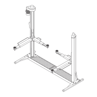
SOLLEVAMENTO
Ruotarel’interruttoregenerale(QS)inposizione1epremereilpul-
santedisalitafinoalraggiungimentodell’altezzadesiderata.
Durantelacorsa,lalevadicomandomartellettirestaintrazionee
pertantoimartellettirimangonodisinseriti
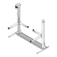
STAZIONAMENTO
IncondizionidistazionamentoilcariconondeveMAIessereso-
stenutodallefuniportanti,madaimartellettidistazionamentoche
quindidevonoessereautomaticamenteinseritinelleasoledelle
astedisicurezza.
Unavoltaraggiuntal’altezzadesideratapremereilpulsantedista
-
zionamento(SB3).
L’arrestodelmovimentoavvieneautomaticamenteallorchéimar
-
tellettisiappoggianosulpianodellaprimaasolacheincontrano
duranteladiscesa.
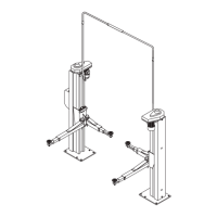
DISCESA
Premereilpulsantedidiscesa(SB2)che,dopounabrevesalita,
sganciaautomaticamenteimartellettiedazional’elettrovalvoladi
discesa.
Ladiscesaverràarrestatadalmicrointerruttoredidiscesa.
PercompletareladiscesabisognarilasciareilpulsanteSB2epre
-
mereilpulsanteSB3,questapartedelladiscesavieneaccompa
-
gnatadaunsegnaleacusticocheavvertedelpericolodischiaccia
-
mentodeipiedi.
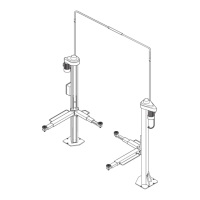
Seduranteladiscesalapiattaformaincontraun’ostacolocheim
-
pedisceilproseguimentodellacorsasihal’interventodeisensori
cheazionanoimicrodisicurezzaallentamentofuniconconse
-
guentearrestodelmovimento.
Inquestasituazioneépossibilecomandaresololasalita.Durante
lafasedidiscesalasicurezzacontrol’accidentalecadutadelvei
-
coloésempreassicuratadalmartellettocomandatodalsensore
allentamentofuni.
CHAPTER5 OPERATING
PRINCIPLESANDUSE
Theliftoperatorcontrolsare:
MAINSWITCH(QSFig.59)
POSITION0:theliftisnotconnectedtothe
electricalsupply;youcanopenthecontrolpa
-
nelandinstallalockoutonthemainswitchto
preventunauthoriseduseoftheunit.
POSITION1:theliftmotorisreceivingelectrical
power,butthisbuttonifusedindividuallydon’t
allowanyliftoperation.Thedoorofthecontrol
panelislockedandcannotbeopenedinadver
-
tently.
LIFTBUTTON(SB1Fig.59)
“Operatorpresent”type,24V;whentheLIFT
buttonispressedthehydrauliccontrolunitwill
startup.
LOWERINGBUTTON(SB2Fig.59)
Alsothisbuttonis“operatorpresent”type,24V;whenpressed,it
activatesthereleasemagnetofthesafetywedgesandthelowe
-
ringsolenoidvalveofthehydrauliccontrolunit.
STOPBUTTON(SB3Fig.59)
Operatorpresent”type,24V;pressingtheSTOPbuttonactivates
theloweringsolenoidvalveinthehydrauliccontrolunit.
PULSANTEDIAVVIO(SB8)
Ifyoupressthisbuttonitgiveselectricalpowertothetransformer.
LIFTING
Setthemainswitch(QS)to1andpresstheLIFTbuttonuntilthe
liftreachesthedesiredheight.
Duringitstravel,thesafetywedgereleaseleverwillremainintrac-
tionsothatthewedgeskeepdisconnected.
STOPPING
Whenavehicleisstoppedintheelevatedposition,theloadmust
NEVER besupportedbytheliftcables,theloadmustinsteadbe
supportedbythestoppingwedgeswhichmustthereforebeenga
-
gedautomaticallyintheslotsonthesafetyrods.
WhenyoureachthedesiredheightpresstheSTOPbutton(SB3).
Themovementwillbehaltedautomaticallyassoonasthewedges
encounterthefirstsafetyrodslotsduringtheinitiallowering.
LOWERING
Presstheloweringbutton(SB2)which,afterashortrise,automati
-
callydisengagesthesafetywedgesandactivatestheloweringso
-
lenoidvalve.Loweringwillbestoppedbyloweringmicroswitch.In
ordertocompletethelowering,thepushbutton(SB2)willhaveto
bereleasedandpushbutton(SB3)willhavetobepressed.Inthe
lastpartoftheloweringanaudiblealarmwillbeheardtoprevent
fromfoottreadingdanger.
Iftheplatformshouldencounteranobstructionduringitslowering
thesensorsthatactivatetheliftcableslacksafetymicroswitches
willoperateandstoptheloweringmovement.
InthissituationonlytheLIFTcontrolisaccepted.Notethatduring
loweringcyclesprotectionagainsttheaccidentalfallingofthevehi
-
cleisprovidedbythesafetywedgecontrolledbytheliftcableslack
sensor(mechanicaloperation).
34
QS
SB2
SB1
SB3
SB8
 Loading...