CAP.1. DESCRIZIONEDELLA
MACCHINA
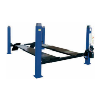
Ipontisollevatoria4colonnesonofissi,cioèancoratialsuolo;
sonoprogettatiecostruitiperilsollevamentoelostazionamentoin
quotadiautoveicoliefurgoni.
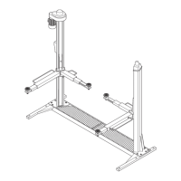
Sonocompostiprincipalmentedaunapartefissa,ancorataalter
-
reno(colonne)edaunapartemobile(traverseepedanedisoste
-
gnoesollevamento).
Ilfunzionamentoèditipoelettroidraulico.
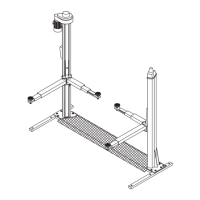
Questisollevatorisonocomposti,fondamentalmentedaquattro
parti:
-gruppostrutturafissa;
-gruppostrutturamobile;
-gruppodisollevamento;
-sicurezze.
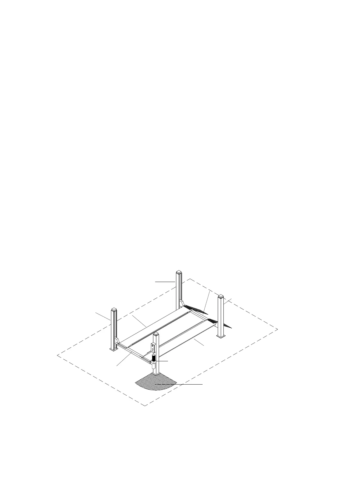
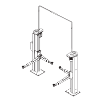
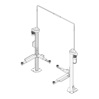
Infigura3sonoindicatelevariepartichecompongonoilsollevato
-
reelezonedilavoroattornoalsollevatorestesso.
Latooperatore:èillatoanterioredelsollevatore,quellochecom
-
prendeanchelazonariservataall’operatoreincuisiaccedeal
quadrocomandiedèoppostaallatodiingressodelsollevatore.
Latoposteriore:èillatooppostoaquellooperatoreincuisitrova
-
nolerampediaccessoalsollevatore.
Latidestroesinistro:sonostabilitirispettoall’operatorerivoltover
-
soilsollevatore.
Zonadirischio:èlazonadirischioincuinonsidevemaisostare
quandoilsollevatoreèinfunzione;spiegazionimaggiormentedet
-
tagliateletroveretenelcapitolo3“Sicurezze”.
Lanumerazioneinfigura3siriferiscea:
1 colonnalatocomando(siintendeper
convenzioneinternacomeanterioredestra)
2 colonnaanterioresinistra
3 colonnaposterioresinistra
4 colonnaposterioredestra
5 traversalatocomando(traversaanteriore)
6 traversatraversaposteriore
7 pedanadestra,fissa
8 pedanasinistra,mobile
Fig.3
CHAPTER1. DESCRIPTION
OFTHEMACHINE
Four-postliftsarefixedinstallations,i.e.anchoredtothefloor;the
unitsaredesignedandbuiltforliftingcarsandvansandholding
theminanelevatedposition.
Theunitsareessentiallymadeupofafixedpartthatisanchored
tothefloor(posts)andamovingpart(cross-piecesandplatforms).
Theoperationiselectro-hydraulic
Therearefourbasicpartsofthelifts:
-fixedstructureassembly;
-movablestructureassembly;
-liftingassembly;
-safetydevices.
Figure3showsthevariouspartsoftheliftandtheoperatingzones
inthesurroundingarea.
Operatorside:thisisthefrontofthelift,includingtheareareser
-
vedfortheoperatorwiththecontrolpanel.Theoperatorsideisop
-
positethevehicleaccessside.
Rearside:itisthesideopposedtheoperator’sone,withtheliftac
-
cessramps.
Rightandleftsides:therightandleftisconsideredfromtheopera
-
tor’sstandpointwhenfacingthelift.
Dangerzone:anareathatmustbekeptclearofpersonswhenthe
liftisinuse;referto“Safetydevices”chapter3fordetails.
Keytofigure3:
1 controlsidepost(conventionallythefrontright-handpost)
2 frontleftpost
3 rearleftpost
4 rearrightpost
5 controlsidecross-piece(frontcross-piece)
6 rearcross-piece
7 rightfixedplatform
8 leftmovingplatform
6
1
5
7
8
4
3
6
2
Zonaoperatore
Operatorzone