FMTRANSMITTER
TREM1000HEDIGPLUSCOMPACT
TechnicalManual1v2November2019 14
1.3.2Rearpaneldescription.
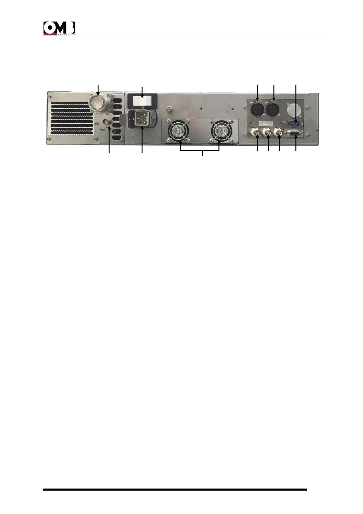
TherearpaneloftheEM1000HEDIGPLUSCOMPACTisshowninthenextpicture
Figure1.2:EM1000HEDIGPLUSCOMPACTRearPanel
Theelementsshowninthepreviousfigurearedescribednext:
1.Antennaoutputsocket/flange(RFOUTPUT)–this7/16”(F)socket/flangeisconnectedto
anFMbroadcastingantennathatcantoleratethetransmitter’snominalpower.
2.Powersocketorcable–usedtoconnecttoamainssupply.
3.Generalpowerswitch(POWERON)–allowstheusertoturnthegeneralsystempoweron
andoff.
4.RIGHT–balancedinput(femaleXLR)formodulationoftherightaudiochannel.Thisinput
canalsoacceptamonosignalformonophonictransmissions.
5.LEFT–balancedinput(femaleXLR)formodulationoftheleftaudiochannel.
6.REMOTEcontrolinput–this9pinSUBDconnectorallowstheusertoremotelycontrolthe
deviceortoperformotherfunctionsviaasuitableinterface.
7.RS232serialprogrammingport–thisfemaleRS232SubD9portwithinvertedcableallows
the user to control the transmitter via a computer or an external pointtopoint control
device.
8.MPX–externallycreatedbroadbandstereocompositemodulatingsignalinput(BNCtype
unbalancedconnectorwithgroundingshield).
9. AUX – auxiliary modulating channel input (RDS/SCA) at low frequency on a 20100 KHz
band (BNCtype unbalanced connector with grounding shield) for connection to an RDS
encoder.
10.MODULATIONMONITORsocket–BFmodulationoutputsockettobeusedasamonitor,
forsynchronizationoftheRDSencoder,orbroadcastretransmission(BNCtypeconnector).
11.Powersupplyfans.
12.PosteriorRFMONITORinput–BNCtypeconnectorforsourcingthelowlevelRFsignal.
Thesignalattenuationis57dB.
12 2 11 10 9 8 7
1 3 4 5 6


 To Next Page