FMTRANSMITTER
TREM1000HEDIGPLUSCOMPACT
TechnicalManual1v2November2019 78
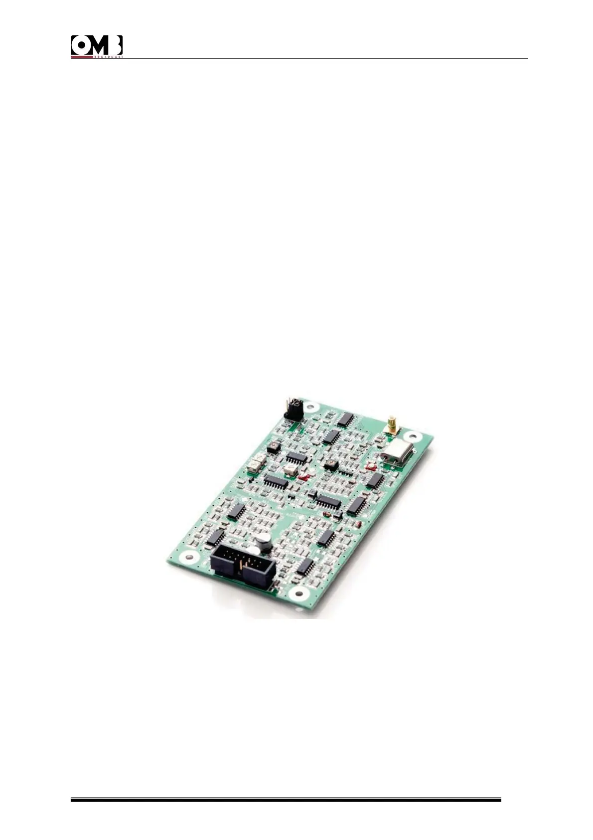
3.11.1STEREOGENERATORBOARD(OPTIONAL)
Thephasecontrolloop(PLL)circuitiscontainedentirelyintheintegratedcircuitIC2,whose
referencefrequencyisgeneratedinaTCXOcalledTCXO1inthediagram.Thesignalgenerated
bythisoscillatorhas afrequencyof12.8MHz.Tooperatecorrectlyinthechosenreference
frequency, the synthesizer circuit IC2 must be programmed serially by the Microcontroller
withcomplexinformation,ataskcarriedoutthroughthreecontrollines.
The integrated circuit IC1, through its two sections, filters the output of the frequency
comparator, both towards the modulating varicap diodes and towards the phasehook
detectioncircuit.
It may be noted that the gate bias voltage is removed from the output MOSFETs through
transistorsTR4and TR3to suspendthe RF outputof theunit whilethe phase controlloop
(PLL)isnotcorrectlyengagedinphaseattheselectedfrequency.Thecontrolloophasbeen
designed to ensure that the crosstalk added to the stereo multiplexed baseband signal is
below55dBat30Hz,beingvirtuallynegligibleathigherfrequencieswithinthebaseband.The
followingfigureshowsthechanneloscillatorcircuitandPLL.
Figure:Stereogeneratorboard