FM TRANSMITTER
TR EM 1000 HE DIG PLUS COMPACT
Technical Manual 1v2 November 2019 69
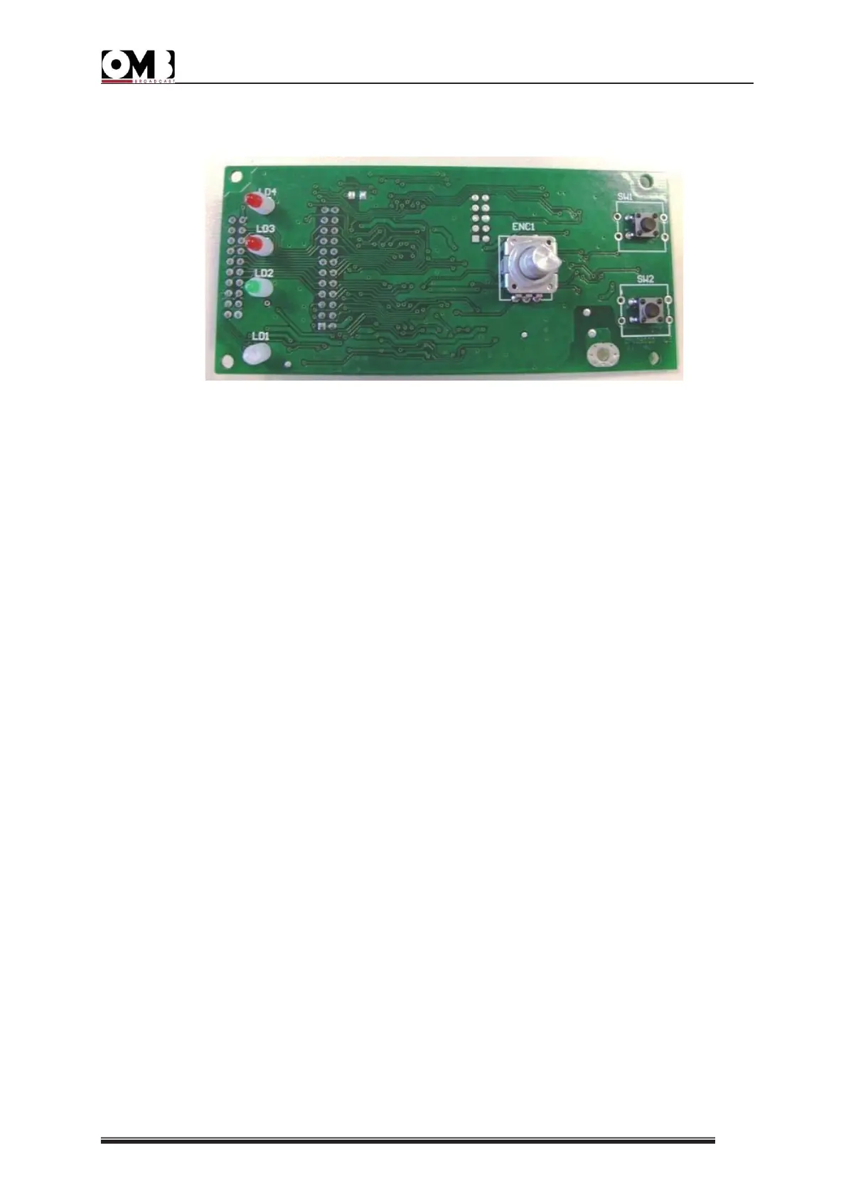
3.6 KNOB ENCODER BOARD
Figure: Knob encoder board
This board is sends the signals that come from the control unit to the DISPLAY.
It also represents the external interface unit through a rotary encoder with pulsation. This
encoder allows managing all the functions of the transmitter by accessing the menus and sub-
menus.
The SW1 and SW2 buttons correspond respectively to ON/STAND-BY and ESC.
The front LEDs have the following functions:
• LD1- “ON/STAND-BY” indicator light (yellow / green). This LED looks two ways:
- It looks yellow when the equipment is in stand-by.
- It looks green when the equipment is in operation.
• LD2- “LOCK” indicator light (green) - This LED is green to indicate that the internal
frequency synthesizer has been locked at the set operating frequency.
• LD3- “LIMITER” indicator light (red) - This LED is red to indicate the maximum
deviation limit has been activated due to an audio signal that is too high.
• LD4 - “ALARM” indicator light (red) - This LED is red if an alarm event occurs (for
example, low output power or low modulation).
 Loading...