FM TRANSMITTER
TR EM 1000 HE DIG PLUS COMPACT
Technical Manual 1v2 November 2019 74
3.9.1 Low Pass Filter
The low pass filter attenuates the harmonics outside band II, at -70dbc levels, being placed in
the drainage circuit of the output transistors.
A directional coupler is also included in this section. It provides forward and reflected
proportional Vdc voltages depending forward and reflected power. It takes a RF sample not
demodulated (MONITOR RF) too, in order to be externally used to make measures with a
modulation monitor or frequency-meter. This signal is present at the BNC female connector
located in the back panel.
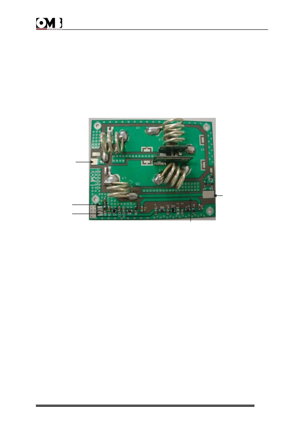
Figure: Low Pass Filter
These are the numbered elements of the filter in the previous image:
1 – Reflected Power Detector.
2 – Direct Power Detector.
3 – Directional Coupler.
4 – RF Input.
5 – RF Output.