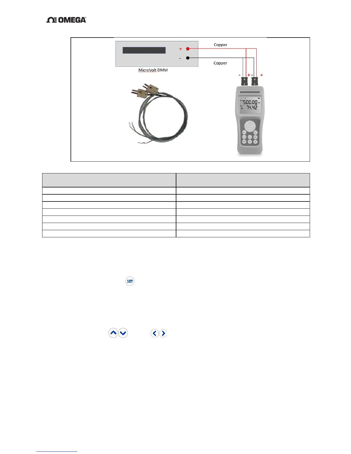
5. Use the Instrument Verification Data Sheet, Appendix C to verify the
measurements in Figure 12 above.
6. Enter setup mode,
(1.5s)
and ensure the following parameters are set: units =
“mV” and rAnGE = “Hi”.
7. Connect the Positive of the Source and Read channels to the positive input of the
DMM. Connect the negative of the Source and Read channels to the negative
input of the DMM.
8. By using the and/or
keys, adjust the instrument Source to match
each value in Figure 12 in the “High range”, notating the result from the DMM on
the “Instrument Verification Data Sheet”, Appendix C in “Source DC Volts Channel
1” “Measurement Result” and “Measure DC Volts Channel 2” “Standard” column.
9. Pass/Fail Criteria:
a) For “Source DC Volts Channel 1”, a PASS result is any “Measurement Result”
value that is equal to or in between the Lower Limit and Upper Limit error
numbers.
 Loading...