4-18
5. Connect the Positive of the Source and Read channels to the positive input of the
DMM. Connect the negative of the Source and Read channels to the negative
input of the DMM.
6. Press UUT to turn the UUT on. Disable the Auto-Power Off press
(1.5s)
CAUTION
Do not apply voltages greater than 83 mV DC to the UUT inputs. Voltages
greater than 83 mV may damage the instrument.
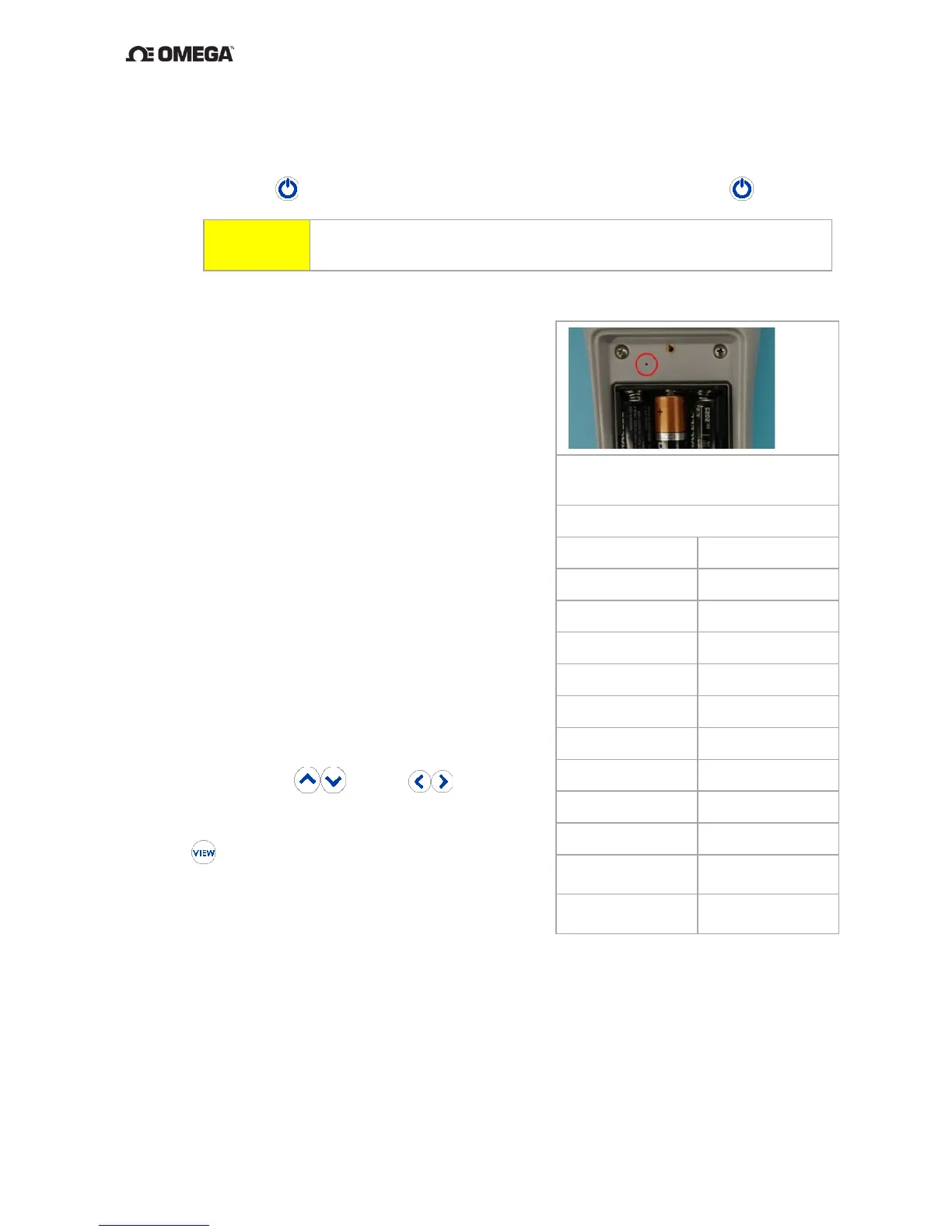
7.
Insert the Straightened Paper Clip through
the alignment access hole and gently press
the calibration enable switch located on the
circuit board to enter CAL mode. See Figure
14 for location.
Temporary calibration values are set to a
gain of 1 and offset of 0 every time
calibration is entered. If the calibration is
accepted and saved without entering new
values, the temporary values are copied to
the system values for use.
Voltage Gain and Offset Alignment
8. The UUT display will indicate as follows:
a. Line 1: “-10.000”
b. Line 2: “CAL 1”
The instrument is now sourcing
-10.000 mV.
9. By using the and/or
keys,
adjust the instrument to match as close as
possible the DMM display voltage. Use the
key to save the settings and advance to
“CAL 2”. Repeat this step to and including
CAL 10.
10. CAL 11 and CAL 12 are used to set the Cold
Junction Compensation, (CJC) of the
Source, (Channel 1) and Read, (Channel 2). These steps require the use of a
customer supplied calibrated temperature measurement device. With the probe as
close as reasonable to the channel 1 CJC, and temperature stabilized, enter the
externally measured temperature in Celsius for channel 1. Repeat this step for
Channel 2, CAL 12. See figure 13 above.
 Loading...