2
CONTENTS
MODEL CONFIGURATION…….………………………………………….…………….2
SPECIFICATIONS………………………………………………………………….……..3
PARAMETER AND SETTING……………………………………………………………4
SYMBOL DESCRIPTIONS…………………………………………..…………………..7
INSTRUMENT INSTALLATION AND WIRING……..………………………….………8
DISPLAY AND OPERATIONS…………………………………………...……….……..9
OPERATION DESCRIPTION……………….…………………..……………….….…10
MODEL CONFIGURATION
Model Description
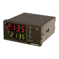
CN4116 (*)-(**)-(***)
1/16 DIN controller
CN4216 (*)-(**)-(***)
1/16 DIN controller, with 0.0 decimal
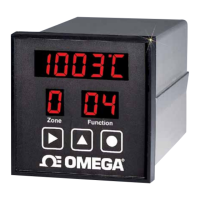
CN414 (*)-(**)-(***)
1/4 DIN controller
CN424 (*)-(**)-(***)
1/4 DIN controller, with 0.0 decimal
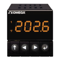
CN418V (*)-(**)-(***)
1/8 DIN Vertical controller
CN428V (*)-(**)-(***)
1/8 DIN Vertical controller, with 0.0 decimal
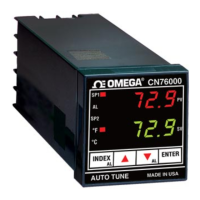
CN418H (*)-(**)-(***)
1/8 DIN Horizontal controller
CN428H (*)-(**)-(***)
1/8 DIN Horizontal controller, with 0.0 decimal
* Specify controlling output code from Output Options table below
** Specify alarm code from Alarm Options table below
*** Low voltage power supply option (-LV)
Controlling Output Options
Option Type Code
Relay -R1
DC SSR driver -DC1
Alarming Output Options
Option Type Code
Relay -R2
DC SSR driver -DC2
Low voltage power supply option
-LV 24V AC/DC, 50/60 Hz
 Loading...