42
3.2.11 Output 2
Output 2 and Alarm 2 share the same contacts on the rear panel connector. If
Alarm 2 is Enabled, Output 2 is automatically Disabled.
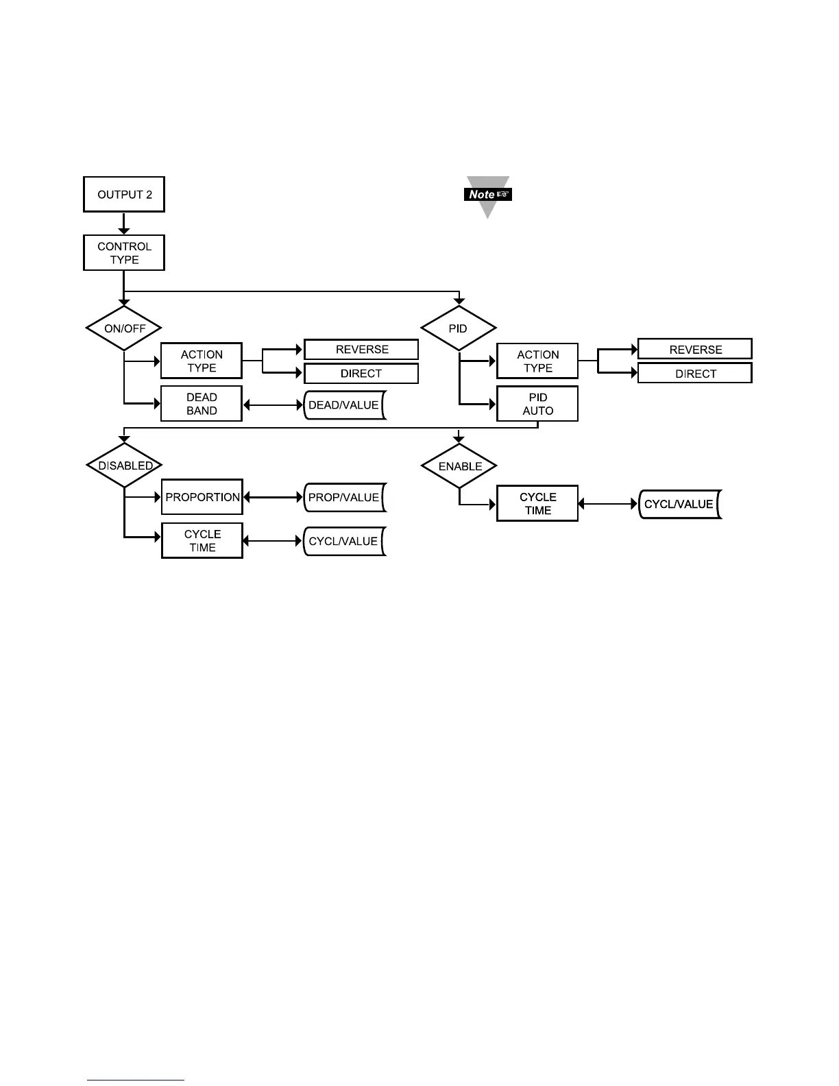
Figure 3.10 Flow Chart for Output 2
ENTER OUTPUT 2 MENU:
Press
a
1) Press
a
, if necessary, until
CNFG
prompt appears.
Press
d
2) Display advances to
INPT
Input Menu.
Press
a
3) Press
a
, if necessary, until Display advances to
OUT2
Output 2 Menu.
Press
d
4) Display advances to
CTRL
Control Type Submenu.
CONTROL TYPE SUBMENU:
Press
d
3) Display flashes
ON.OF
ON/OFF, or
PID
PID.
Press b 4) Scroll through the available selections: “ON/OFF” or “PID”.
Press
d
5) Display shows
STRD
stored message momentarily and then
advances to
AçTN
only, if it was changed, otherwise press
a
to
advance to
AçTN
Action Type Submenu.
The ON/OFF control is a coarse way of controlling the Process. The “Dead
Band” improves the cycling associated with the ON/Off control. The PID control
is best for processes where the Setpoint is continuously changing and/or tight
control of the Process Variable is required.
It is required that you put
the controller in the
Standby Mode for any
configuration change other
than Set Points & Alarms.

 Loading...


