20
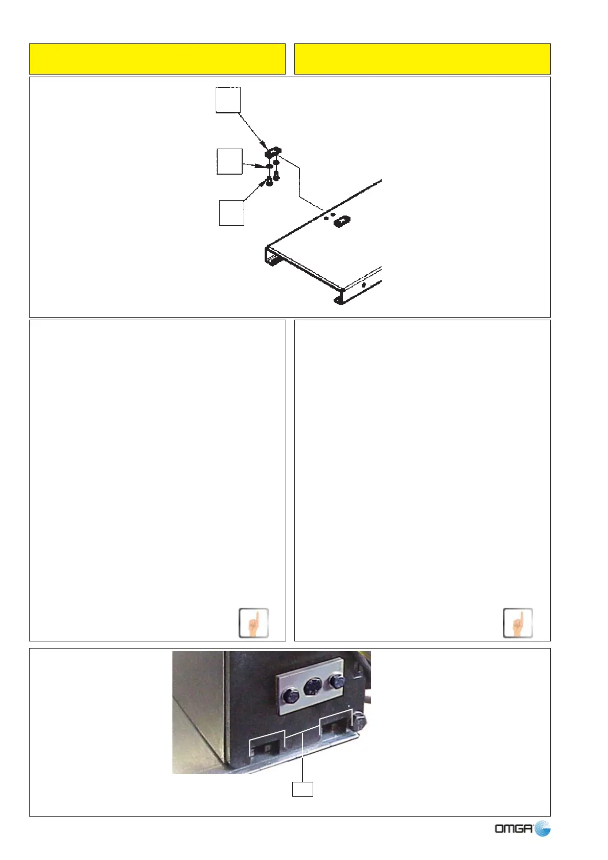
The holes for fi xing the beam to its bench must be made
on its external side (see example above). Make sure
that the holes are suitable for the screws (2) that must
then be screwed into the fi xing plates (1).
The fi xing plates (1) must fi rst be inserted into the
guides underneath the beam in position (H, “Tensioning
of toothed belt” chapter), see photograph at the top of
the page alongside.
Insert them in pairs: two on the left end of the cross-
piece, two in the centre and two on the right end.
Once the plates are inserted, the user must align their
holes on the screws (2) and relative washers, which will
have fi rst been passed across the sliding surface of its
bench and which must have been temporarily held in
position with adhesive tape.
If the operation has been carried out as described, the
beam will be correctly locked on the bench in a stable
and safe manner.
I fori per bloccare la trave sul proprio banco devono
essere praticati sul lato esterno di esso (vedi esempio
qui sopra); si consiglia di praticare questi fori in modo
che siano adatti a farvi passare le viti (2), che devono
poi essere avvitate nei piatrini di bloccaggio (1).
I piastrini di bloccaggio (1) devono prima essere infi -
lati nelle apposite guide sotto la trave in posizione (H,
capitolo “Tensione della cinghia dentata”), vedi foto a
lato in alto.
Si consiglia di infi larli a coppie: due alla estrema sinistra
della trave, due al centro e due all’estrema destra.
Infi lati i piastrini, l’Utilizzatore dovrà poi centrarne i fori
con le viti (2) e relative rondelle, che prima avrà fatto
passare attraverso il piano del proprio banco e che vi
avrà temporaneamente trattenuto con nastro adesivo.
Se l’operazione è stata eseguita come descritto, la trave
sarà correttamente bloccata al banco in modo stabile
e sicuro.
GUIDA AL MONTAGGIO ASSEMBLY GUIDE
1
5
2
H