15
Connections and Interfaces
5.5 LL out 1 - 6 and LL out 7 - 12 (Low Level Outputs)
The interface connectors “LL out 1 - 6” and “LL out 7 - 12” hold a total of 12 independent
high accuracy analog signal outputs. These Test Universe-controlled signal sources can
serve to either drive external amplifiers or to directly provide small signal outputs.
The low level outputs are short-circuit-proof and continually monitored for overload. They
deliver calibrated signals in the range from 0 ... 7 V
eff
nominal (0 ... ± 10 V).
For technical data, → “Low Level Outputs “LL out 1 - 6” and “LL out 7 - 12”” on page 18.
Overload Warning in the Test Software
When a low level output is overloaded, the test software issues an appropriate warning. Refer to the
Test Universe or RelaySimTest Help for more details.
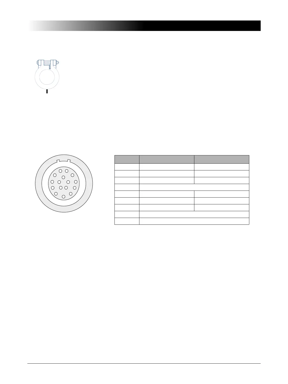
Pin assignment
“LL out 1-3”, “LL out 4-6”, “LL out 7-9” and “LL out 10-12” each make up a selectable voltage or current
triple.
Pin Function LL out 1-6 Function LL out 7-12
Pin 1 LL out 1 LL out 7
Pin 2 LL out 2 LL out 8
Pin 3 LL out 3 LL out 9
Pin 4 Neutral (N) connected to GND
Pin 5 LL out 4 LL out 10
Pin 6 LL out 5 LL out 11
Pin 7 LL out 6 LL out 12
Pin 8-16 For internal purposes
Housing
Screen connection
 Loading...