© OMICRON 2024 Page 16 of 25
COMPANO
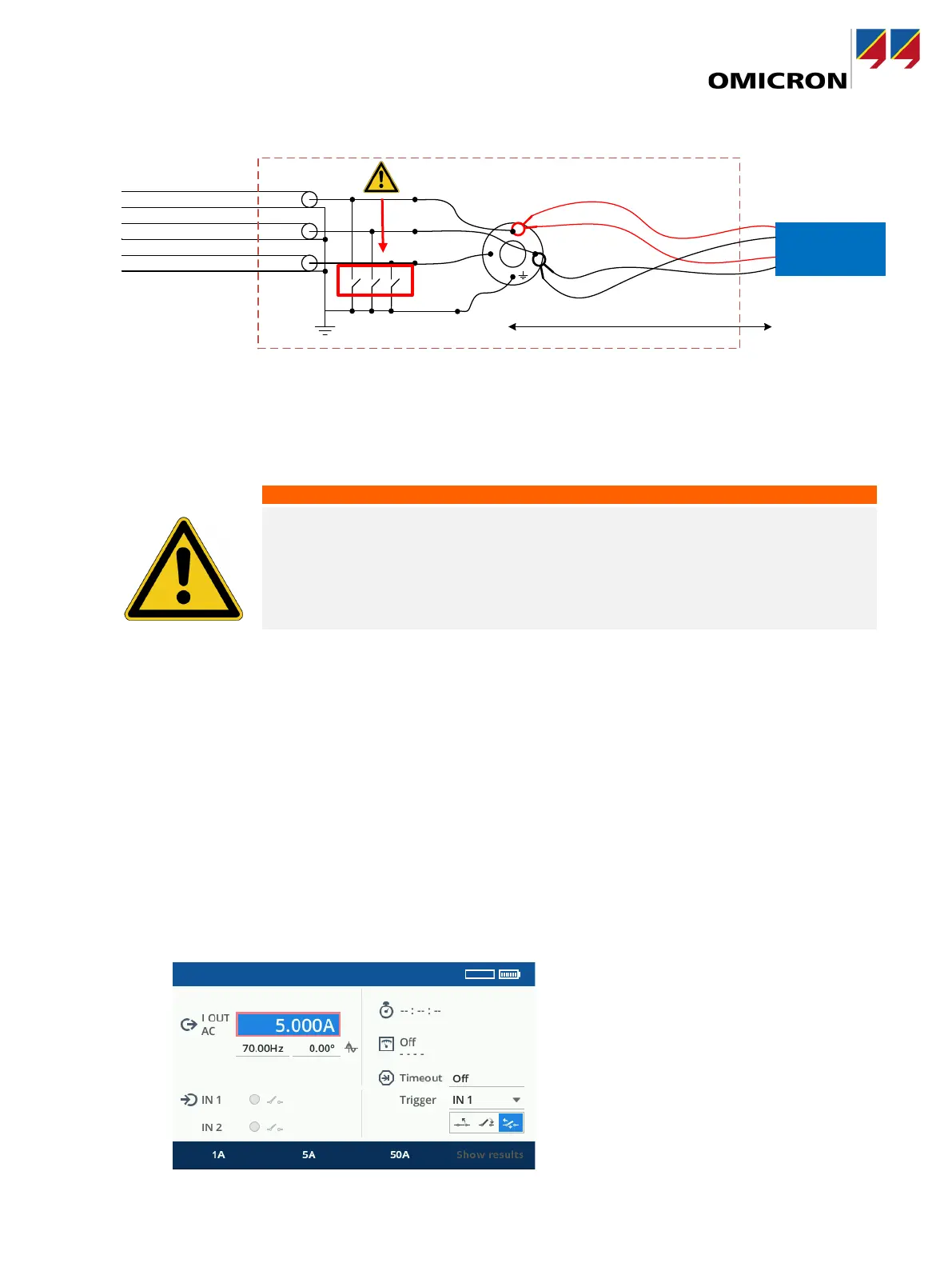
100
I OUT
IN1
Distance ≥ 5 m / 15 ft
Cabl e len gt h
≥ 10 m / 3 0 ft
Figure 6: Connecting COMPANO 100 to CP GB1
To connect COMPANO 100 to CP GB1, perform the following steps:
1. Make sure the grounding switch is closed!
Death or severe injury caused by high voltage or current possible.
Position COMPANO 100 outside the danger zone. Keep a distance of at
least 5 m / 15 ft between CP GB1 and COMPANO 100.
Use measurement leads of at least 10 m / 30 ft length.
2. Position
COMPANO 100 outside the danger zone, at least 5 m / 15 ft from the CP GB1.
3. Ground COMPANO 100, using a cable of at least 6 mm² cross-section, close to the position of the
operator.
4. Connect COMPANO 100 to CP GB1 as shown in Figure 6 using measurement leads of at least 10
m / 30 ft length.
5. Leave the danger zone and open the grounding switch.
To inject the test current, perform the following steps:
1. Select the COMPANO 100 QUICK application module.
2. Configure it for 5 A at a frequency of 70 Hz (on 50 Hz systems) or 80 Hz (on 60 Hz systems).
While connecting COMPANO to the grounding
set, the grounding switch must be closed!