Installation on 3/4” Copper Pipe:
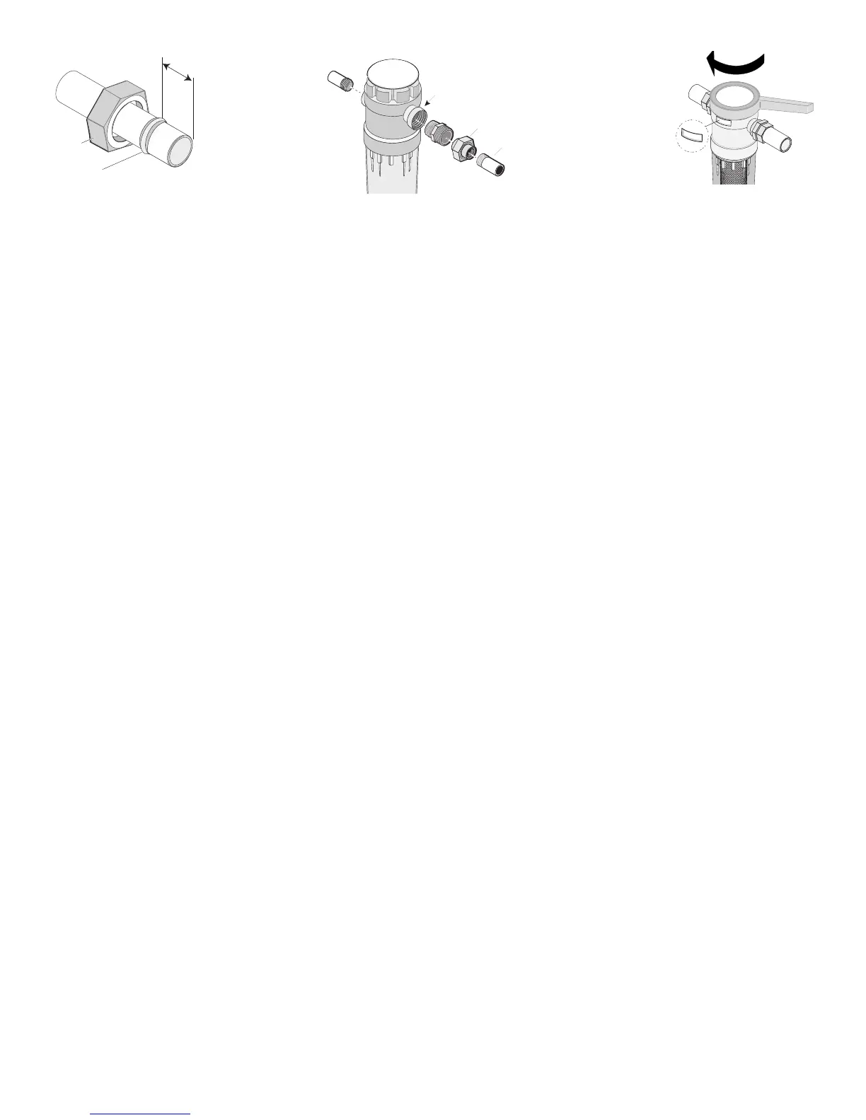
5. Place the lock nuts on the pipe, small end first. Follow the lock
nuts with the brass compression sleeves (one for each cut pipe
end). Slide each brass compression sleeve up 1/4” from the cut
end of the pipe (see Figure 3).
6. Thread the brass compression fittings into the ports in the hous-
ing. Be sure that the smaller 3/4“ NPT end of the fitting goes into
the port. Tighten the compression fittings with the 1-1/4”
wrench until they are snug. DO NOT OVERTIGHTEN.
7. Place the filter (with its fittings) in position on the pipe. Be sure
that the port marked “IN” is on the side toward the water meter
so that the flow enters the filter through this port.
8. Insert the copper pipe into the inlet, making sure that the copper
pipe bottoms out inside the filter head. Tighten the left-hand lock
nut securely with the wrench. Hold the fitting with a wrench to
prevent overtightening it in the housing.
9. Repeat Step 8 with the outlet compression fitting, sleeve, and
nut. Skip to Step 10 under “All Installations”.
Installation on Galvanized Pipe:
5. Thread the cut pipe ends and clean all traces of cutting oil, rust,
hardened pipe compound, etc., from all threads that will be
attached to the unit. Clean the pipe threads with paint thinner or
solvent (NOT gasoline) and dry them with a clean rag; remove all
chips; polish and deburr. Use only teflon tape (without adhesive
backing) on the pipe threads attached to this unit.
6. Apply teflon tape three turns around the threads of the pipe
coming from the water meter. Using the “IN” port, hand screw
the filter onto the water pipe until it is tight. Removing the tank
will make this easier. DO NOT OVERTIGHTEN.
7. Wrap three turns of teflon tape around each end of the 2” nipple
and screw one end into the “OUT” port on the filter. Screw the
union onto the other end of the nipple.
8. Wrap the remaining pipe thread with teflon tape and screw the
other side of the union onto it until tight.
9. Assemble the union and tighten the large nut securely. Make sure
that the pipe ends align and that the union is clean for a water-
tight fit (no tape or compound on the union-half threads). See
Figure 4.
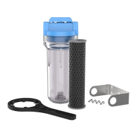
All Installations:
10.Install the filter cartridge in the Cartridge Tank.
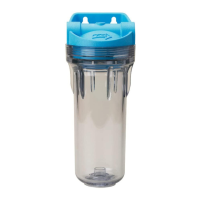
11.To avoid flooding and water damage, make sure that the
O-Ring between the housing and the tank is in good condition
and pr
operly seated in its gr
oove when r
eassembling the unit.
12.The filter is now ready to test. Turn the filter top (using the blue
wrench supplied with the filter) clockwise to “OFF”. Slowly open
the main water supply valve and check for leaks. Turn the filter
top (again using the wrench) from “OFF” to “FILTER”. If any fit-
tings or joints leak, tighten slowly until the dripping stops.
13.Open the faucet and flush the filter for at least 10 minutes after
installation to r
emove the trapped air
. Flush the unit for at least
10 seconds ever
y time you use water for drinking or cooking,
especially if the water tap is not used daily.
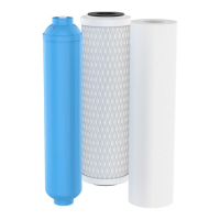
WHEN TO CHANGE THE CARTRIDGE
The cartridge’s life depends on the water volume used and the
substances in the water. Normally the cartridge should be changed
at intervals of ninety days or less. Replace it sooner if the water
ressure at the faucet begins to drop noticeably or if you notice
changes in the taste, color, or flow of the filtered water.
NOTICE: Certain types of harmless bacteria will attack cellulose material.
Cartridges containing cellulose may seem to disintegrate, produce a
“sewer” or “rotten egg” odor, or form a black precipitate due to bac-
teria. If this happens, consult OMNIFILTER Customer Service for advice.
PROCEDURE FOR CARTRIDGE CHANGE
1. Place a pan under the unit to catch any spilled water and open
the nearest faucet.
2. Turn the filter top (using the blue wrench supplied with the
cartridge) clockwise about 45° to “OFF” (see Figure 5).
3. Fit the wrench onto the ribs of the tank and turn it slowly to the
left to release the pressure and loosen the tank.
4. Support the tank as you unscrew it. Pour out the water from the
tank and remove and discard the old cartridge. Wipe the inside
of the tank clean and dry with a soft cloth.
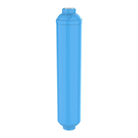
5. Insert a new cartridge into the tank, making sure that it seats
over the center post on the tank bottom.
6. Lubricate the tank O-ring with a good grade of silicone grease or
food-grade vegetable oil and check it for damage. If cut, abrad-
ed, or stretched, replace it with a new one.
7. Screw the filter tank back onto the filter housing. Hand-tighten
the tank. DO NOT OVER TIGHTEN.
8. Turn the top of the filter to “FILTER” with the filter wrench.
NOTICE: If the tank O-ring leaks after you have tightened the tank
with the wrench, DO NOT tighten it anymore. Instead, loosen it and
make sur
e that the car
tridge is seated over the center tube in the
head assembly (not pushing against it). After centering the cartridge,
r
e-tighten the tank and again check for leaks.
9. Open a faucet for about 10 minutes to allow any accumulation
of air, fines, etc., to flush out.
NOTICE: Use only genuine OMNIFILTER replacement cartridges for
best r
esults. Failur
e to use OMNIFIL
TER replacement cartridges will
void your warranty.
TO BYPASS THE FILTER
When watering lawns or doing other projects that don’t require fil-
tered water, the U25 Series B Complete Household Water Filter
System can be bypassed.
1. Turn the filter top (using the blue wrench supplied with the car-
tridge) clockwise about 45
°
to “BY
-P
ASS”. Refer to Figure 5 under
the “Pr
ocedure for Cartridge Change.” section.
2. To continue use of the Filter System, turn the filter top (using the
blue wrench supplied with the cartridge) counter-clockwise about
45° to “FILTER”.
Figure 4
Figure 5
3
Figure 3
1/4"
Compression
Slee
ve
Lockn
ut
Filter Ports
Water Flow
Pipe Union
Threaded,
Galvanized
Pipe End
2
”
pipe nipple

 Loading...