31
Control circuit
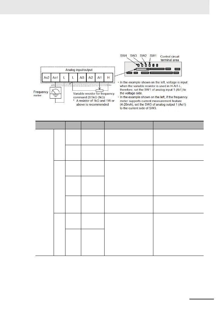
■Analog input/output
(Wiring example)
Terminal
symbol
Terminal name Description Electrical characteristics
Analog input
terminal for
switching
voltage and
current
Power
supply
L Analog
power common
Common terminals for analog input
terminals (Ai1, Ai2, Ai3) and analog
output terminals (Ao1, Ao2). There
are two L terminals.
H Power supply
for setting speed
This is a DC10V power supply. It is
used when using analog input termi-
nals (Ai1, Ai2, Ai3) and variable
resistor for inputting voltage.
Maximum allowable input current
20mA
Analog
input
Ai1 Analog
input terminal 1
(voltage/current
switching SW1)
For Ai1 and Ai2, DC0-10V voltage
input and 0-20mA current input can
be switched using a switch for use.
It can be used for input frequency
command or feedback.
In the case of voltage input:
• Input impedance about 10kΩ
• Allowable input voltage DC-0.3V to
12V
In the case of current input:
• Input impedance about 100Ω
• Maximum allowable input current
24mA
Ai2 Analog
input terminal 2
(voltage/current
switching SW2)
Ai3 Analog
input terminal 3
-10V to 10V voltage input is avail-
able. It can be used for input fre-
quency command or feedback.
Only voltage input:
• Input impedance about 10kΩ
• Allowable voltage input -12V to
12V
Analog
output
Ao1 Analog
output terminal 1
(voltage/current
switching SW3)
For Ao1 and Ao2, DC0-10V voltage
output and 0-20mA current output
can be switched using a switch as
output of information monitor data of
the inverter.
In the case of voltage output:
• Maximum allowable output current
2mA
• Output voltage accuracy ±10%
(ambient temperature: 25°C±10°C)
In the case of current input:
• Allowable load impedance 250Ω or
below
• Output current accuracy: ±20%
(ambient temperature: 25°C±10°C)
Ao2 Analog
output terminal 2
(voltage/current
switching SW4)
 Loading...


