33
Control circuit
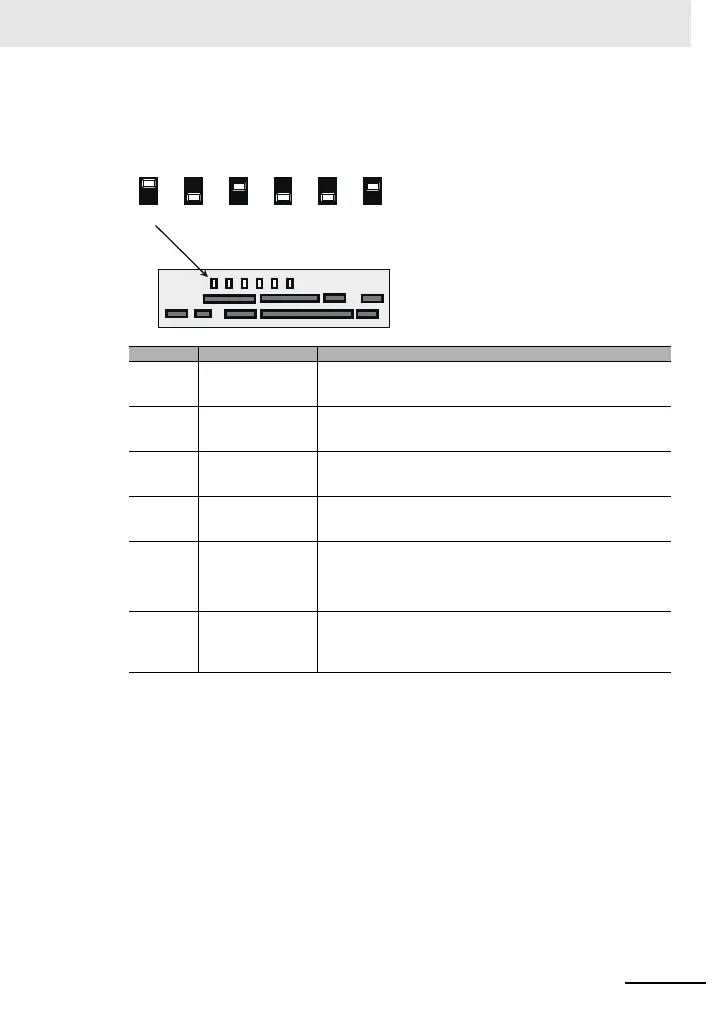
■Description of switches
Indication SW name Description
Ai1
(SW1)
Analog input 1 switch
Switches input specification of analog input 1 (Ai1 terminal).
10V: Voltage input is available.
20mA: Current input is available.
Ai2
(SW2)
Analog input 2 switch
Switches input specification of analog input 2 (Ai2 terminal).
10V: Voltage input is available.
20mA: Current input is available.
Ao1
(SW3)
Analog output 1 switch
Switches output specification of analog output 1 (Ao1 terminal).
10V: Output changes to voltage output.
20mA: Output changes to current output.
Ao2
(SW4)
Analog output 2 switch
Switches output specification of analog output 2 (Ao2 terminal).
10V: Output changes to voltage output.
20mA: Output changes to current output.
P.SEL
(SW5)
Switching the method of
power supply to the input
terminals
Switches the method of power supply to the input terminals.
IN: Drives the input terminals using the internal power supply.
EX: Use an external power supply to drive input terminals.
(In the case of EX, a power supply is required between the input terminals
and COM.)
SRC/SINK
(SW6)
Switch of sink/source for
the input terminals
Switches the sink/source logic for input terminals.
This switch is enabled when SW5 is IN.
SINK: Enables sink logic.
SRC: Enables source logic.
Control circuit terminal area
SW4
SW3
SW2
SW1
SW5
SW6
10V
20mA
10V
20mA
10V
20mA
10V
20mA
IN
EX
SINK
SRC
Ao2 Ao1 Ai2
Ai1 P.SE
(SW4) (SW3) (SW2) (SW1) (SW5) (SW6)(SW4) (SW3) (SW2) (SW1) (SW5) (SW6)
* Using a switch under power-on condition may cause
failure. Use the switch only after turning off the
power and confirming that the POWER lamp on the
operator keypad is off.
(Factory setting)
 Loading...


