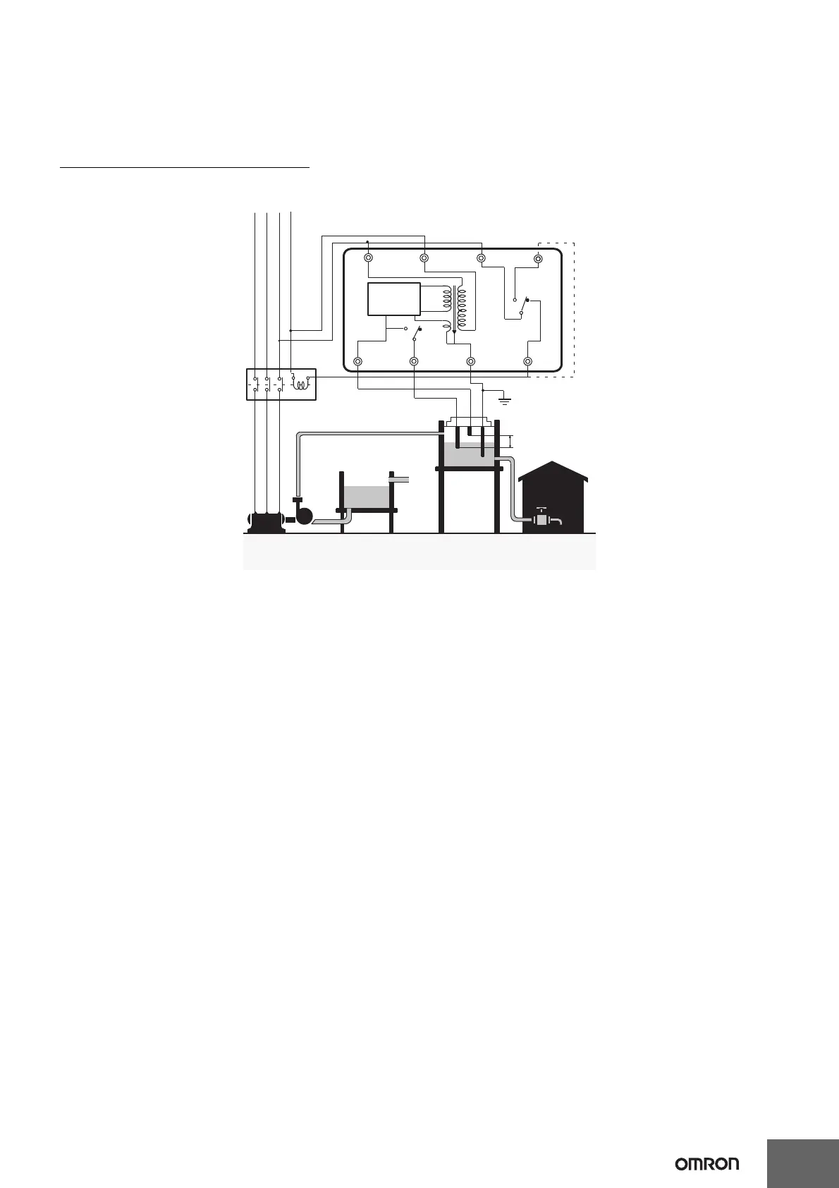
EasyManuals Logo

Omron 61F-GP-N User Manual

Omron 61F-GP-N
15 pages
To Next Page IconTo Next Page
To Previous Page IconTo Previous Page
Page #13 background imageLoading...
Page #13 background image
13
61F-GP-N@
Connection with Three-phase Four-line Circuit
When supplying power from N-phase to the Controller in three-phase four-line circuit, refer to the following diagrams.
Line voltage (R-S, S-T, or R-T): 380 or 415 VAC
Phase voltage (N-R, N-S, or N-T): 220 or 240 VAC
61F-GP-N8@, 220 or 240 VAC
Note: Be sure to ground terminal 1.
Power source
380 to 415 VAC
R S T N *
M
Water tank
Stop
Start
E2
E3
E1
P
6
Electromagnetic switch
Transformer
43
7
5
12
U
24 V
8 V
A
*
U
Control
circuit
8
Water supply source

Questions and Answers:

Question and Answer IconNeed help?

Do you have a question about the Omron 61F-GP-N and is the answer not in the manual?

Omron 61F-GP-N Specifications

General IconGeneral
Control OutputRelay
Contact ConfigurationSPDT
Rated Current5A
Rated Voltage250 VAC
Operating ForceNot Applicable
Operating Temperature Range-10 to 55°C
Electrical Life100, 000 operations
Contact Rating5A at 250 VAC
Mounting TypePanel
ElectrodeSeparate Electrode Required
Mechanical Life5, 000, 000 operations
Supply Voltage100/110/120 VAC, 200/220/240 VAC

Related product manuals