61F-GP-N@
6
Replacing 61F-G3N Functions
Replacing 61F-G3N Functions (Automatic Water
Supply Control with Abnormal Water Increase and
Water Shortage Alarms)
Compact, Plug-in Type
61F-GP-N
Dimensions:
page 14
E1
E2
E4
E5
Contactor
Water supply
source
Stop
Full tank
Start
Water shortage
MCCB
RS
M
T
Commercial Voltage
Water shortage Pump control Full tank
P
PS-5S
E3
U3
U
3
61F-GP-N
56
7
8
4
8 V
Power
supply
Power
supply
Power
supply
0 V
24 V
10
3 9
12
11
Control
circuit
U3
U1
U
1
61F-GP-N
5
678
4
8 V
0 V
24 V
10
3 9
12
11
Control
circuit
U1
U2
U
2
61F-GP-N
5678
4
8 V
0 V
24 V
10
3 9
12
11
Control
circuit
U2
B
PL PL
(See note.)
Upper limit
Lower limit Alarm
Water
tank
Motor protection
relay
Note: The power supply phases (terminals 3 to 9) can be matched to use the same ground for the common Electrode
(the longest Electrode, terminal 4).
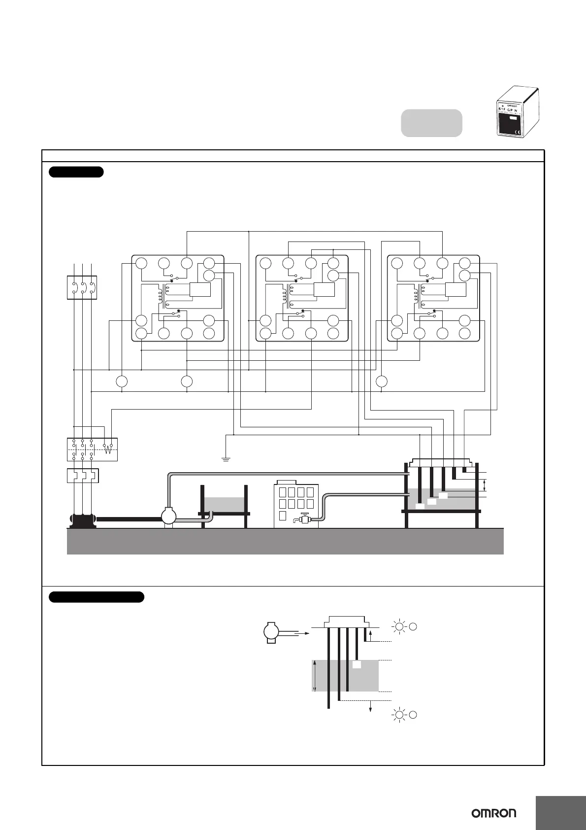
Connections
E1
E3
E4
E5
Upper
limit
Lower
limit
Pump OFF
Pump ON
(U
1
indicator ON)
(U
2
indicator ON)
(U
2
indicator OFF)
(U
3
indicator OFF)
B
LH
B
LL
P
Water supply
E2
• The pump stops when the water level
reaches E
2 (U2 indicator ON) and starts
when the water level drops below E
3 (U2
indicator OFF).
• If the water level rises to E
1 for any reason,
the upper-limit indicator turns ON and the
alarm sounds (U
1 indicator ON).
If the water level drops below E
4 for any
reason, the lower-limit indicator turns ON
and the alarm sounds (U
3 indicator OFF).
Principles of Operation

 Loading...