4
1. Preparation
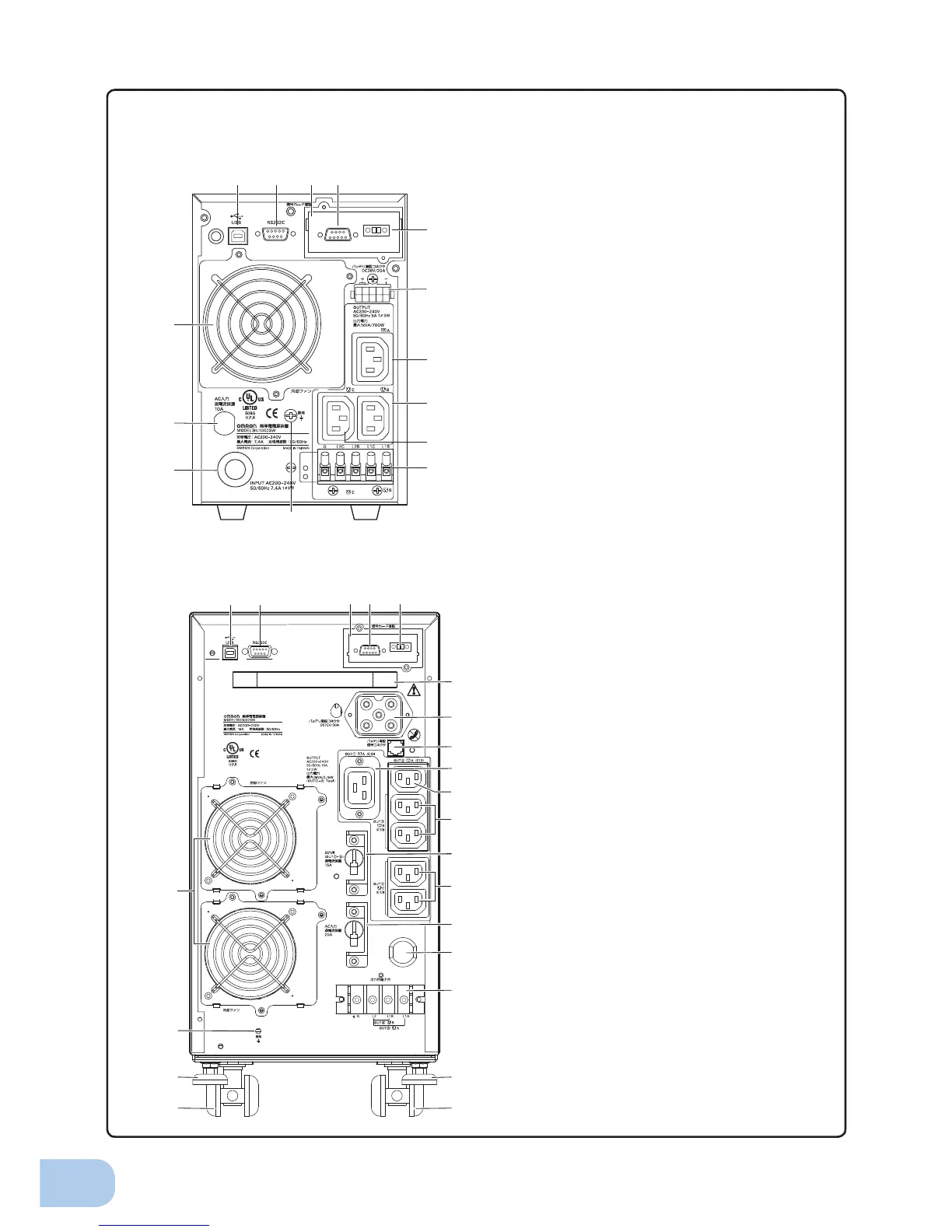
Rear view
A. USB connector
B. RS-232C connector
C. Contact signal card
D. Contact signal connector
E. Remote ON/OFF connector
F. Additional battery connector
G. Power supply output receptacle A (IEC60320 C13)
H. Power supply output receptacle B (IEC60320 C13)
I. Power supply output receptacle C (IEC60320 C13)
J. Terminal block for output
K. Grounding terminal
L. AC input cable
M. AC input overcurrent protection
N. Cooling fan
<BU1002SW>
A
K
M
L
N
B C D
F
E
G
I
H
J
MAX
A B
C D
F
E
G
H
K
J
I
L
M
N
O
P
Q
R
Q
R
S
T
SeeinstallationInstructions
beforeconnectingtothesupply.
NotForCurrentInterrupting.
Refertotheinstructionmanualforthe
tighteningtorque.
UseCopperConductor
Only.
INPUTAC200–240V
50/60Hz16A1ø3W
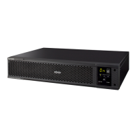
<BU3002SW>
A. USB connector
B. RS-232C connector
C. Contact signal card
D. Contact signal connector
E. Remote ON/OFF connector
F. Handle
G. Additional battery connector
H. Additional battery signal connector
I. Power supply output receptacle A (IEC60320 C19)
J. Power supply output receptacle A (IEC60320 C13)
K. Power supply output receptacle B (IEC60320 C13)
L. Overcurrent protection switch for output 15A
M. Power supply output receptacle C (IEC60320 C13)
N. AC input overcurrent protection switch 20A
O. AC input cable
P. Terminal block for output
Q. Fixed stand
R. Casters
S. Grounding terminal
T. Cooling fan