130
Operating Procedure Section 4-2
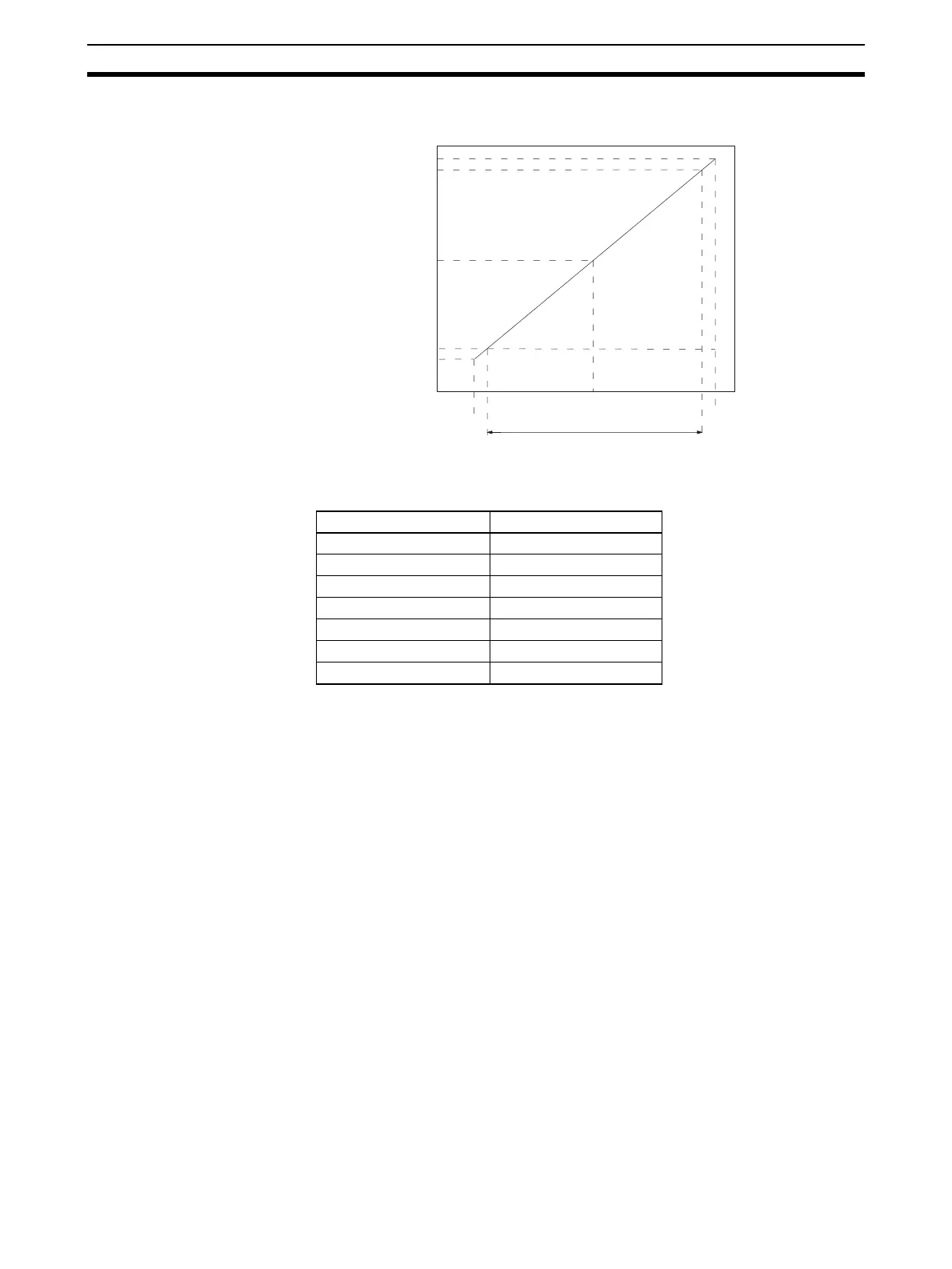
Range: −10 to 10 V
Note The set values for a range of –10 to 10 V will be as follows:
4-2 Operating Procedure
Follow the procedure outlined below when using Analog Output Units.
Installation and Settings
1,2,3... 1. Set the operation mode switch on the rear panel of the Unit to normal
mode.
2. Wire the Unit.
3. Use the unit number switch on the front panel of the Unit to set the unit
number.
4. Turn ON the power to the PLC.
5. Create the I/O tables.
6. Make the Special I/O Unit DM Area settings.
• Set the output numbers to be used.
• Set the output signal ranges.
• Set the output hold function.
7. Turn the power to the PLC OFF and ON, or turn ON the Special I/O Unit
Restart Bit.
When the output for the connected devices needs to be calibrated, follow the
procedures in Offset and Gain Adjustment below. Otherwise, skip to Opera-
tion below.
0000
F830
F768
07D0
0898
0 V
–10 V
–11 V
11 V
10 V
Resolution: 4,000
Set value (16-bit binary data)
Analog output signal
16-bit binary data BCD
F768 –2200
::
FFFF –1
0000 0
0001 1
::
0898 2200
 Loading...


