195
Exchanging Data with the CPU Unit Section 5-5
CJ1W-DA08V/08C
Note For the CIO word addresses, n = CIO 2000 + unit number x 10.
Set Values and Stored Values
Allocation for Adjustment
Mode
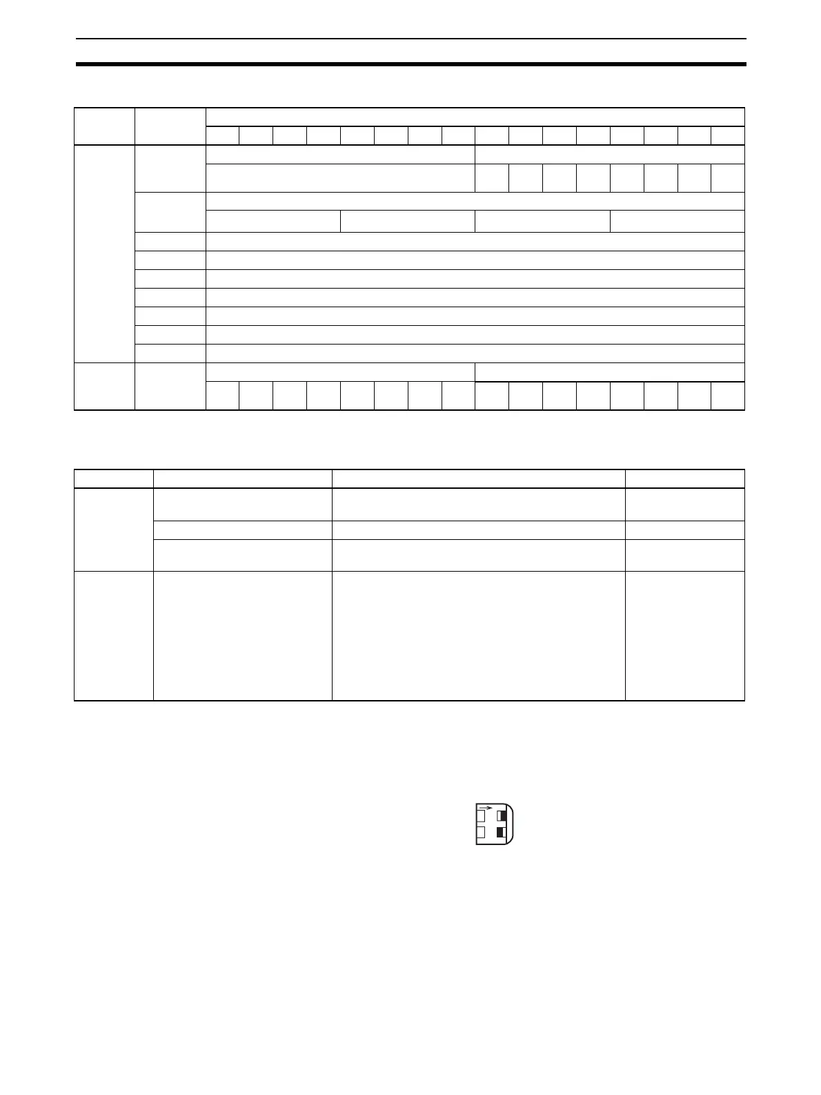
For adjustment mode, set the operation mode switch on the front panel of the
Unit as shown in the following diagram. When the Unit is set for adjustment
mode, the ADJ indicator on the front panel of the Unit will flash.
(The CJ1W-DA08V/08C does not have this switch. Change the mode by set-
ting bits 00 to 07 in D(m+18) to C1 hex.)
I/O Word Bits
1514131211109876543210
Output
(CPU to
Unit)
n Not used. Conversion enable
---
Out-
put 8
Out-
put 7
Out-
put 6
Out-
put 5
Out-
put 4
Out-
put 3
Out-
put 2
Out-
put 1
n + 1 Output 1 set value
16
3
16
2
16
1
16
0
n + 2 Output 2 set value
n + 3 Output 3 set value
n + 4 Output 4 set value
n + 5 Output 5 set value
n + 6 Output 6 set value
n + 7 Output 7 set value
n + 8 Output 8 set value
Input
(Unit to
CPU)
n + 9 Alarm Flags Output setting error
Out-
put 8
Out-
put 7
Out-
put 6
Out-
put 5
Out-
put 4
Out-
put 3
Out-
put 2
Out-
put 1
I/O Item Contents Page
Output Conversion enable 0: Conversion output stopped.
1: Conversion output begun.
199
Set value 16-bit binary data 198
Output setting error 0: No error
1: Output setting error
203
Common Alarm Flags Bits 00 to 03: Output setting error
Bits 04 to 07: Not used.
Bit 08: Scaling data setting error
Bit 10: Output hold setting error
Bit 11: Not used.
Bit 12: Conversion time/resolution or opera-
tion mode setting error
Bit 15: Operating in adjustment mode
(Always 0 in normal mode.)
193, 216
O
N
12
MODE
ON
OFF
 Loading...


