202
Analog Output Functions and Operating Procedures Section 5-6
generated and scaling cannot be executed. Operation starts normally
when both the upper and lower limits are set to 0000 (the default values).
Setting Upper and Lower
Limits for Output Scaling
Set the scaling upper and lower limits for outputs 1 and 2 in words D(m+19) to
D(m+22) of the DM Area, as shown below.
Note For decimal numbers
−32,000 to +32,000, set 16-bit binary data (8300 to
7D00).
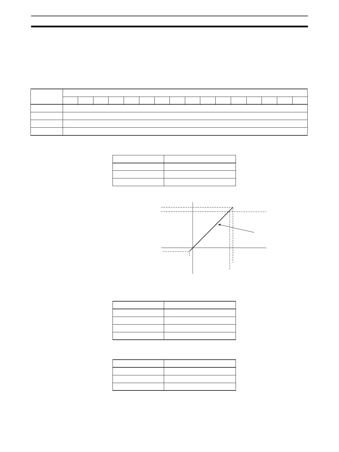
Example Setting 1 Set the following conditions in D(m+19) to D(m+22). (The values shown in
parentheses are binary data.)
When Output Signal Range is 0 V to 10 V
The following table shows the correspondence between output signals and
converted scaling values. (The values shown in parentheses are 16-bit binary
data.)
Example Setting 2
(Reverse Scaling)
Set the following conditions in D(m+27) to D(m+34). (The values shown in
parentheses are binary data.)
DM word Bits
1514131211109876543210
D(m+19) Output 1 scaling lower limit
D(m+20) Output 1 scaling upper limit
D(m+21) Output 2 scaling lower limit
D(m+22) Output 2 scaling upper limit
Setting condition Set value
Output signal range 0 to 10 V
Scaling lower limit 0000 (0000)
Scaling upper limit 10,000 (2710)
Output set value Output signal
0000 (0000) 0 V
10,000 (2710) 10 V
−500 (FE0C) −0.5 V
10,500 (2904) 10.5 V
+10.5 V
+10 V
0 V
−0.5 V
0000 (0000)
−500 (FE0C)
Scaling line
10500 (2904)
10000 (2710)
Setting condition Set value
Output signal range 0 to 10 V
Scaling lower limit 10,000 (2710)
Scaling upper limit 0000 (0000)
 Loading...


