21
Operating Procedure Section 2-2
select either voltage input or current input by wiring the connector termi-
nals. Use DM word m+52 to select 1 to 5 V or 4 to 20 mA as the voltage or
current input range, respectively.
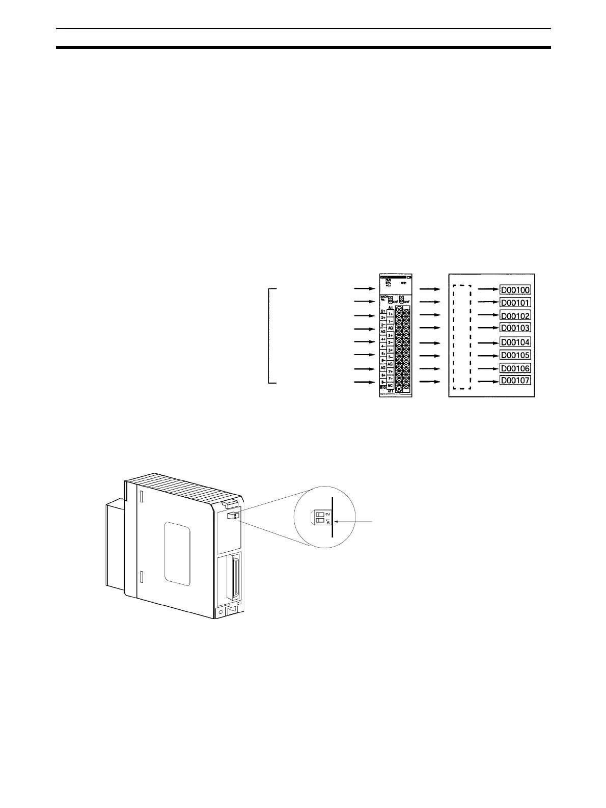
3. Setting the Unit Number
Set the unit number for the Special I/O Unit using the rotary switches on
the front panel of the Unit.
Set the CS1W-AD041-V1 and CS1W-AD081-V1 between 0 and 95. A sin-
gle CS1W-AD161 is allocated words in the CIO Area and DM Area for two
Units. Set the unit number between 0 and 94. To set a CS1W-AD161 to unit
number "n," the unit number setting "n+1" is not possible.
2-2-1 Procedure Examples
The procedure for using Analog Input Units is provided here using the CS1W-
AD081-V1 as an example. The method used to set CS1W-AD161 Analog
Input Units is different. Be sure to use the correct procedure.
Setting the Analog Input Unit
1,2,3... 1. Set the operation mode. Refer to 2-3-3 Operation Mode Switch for further
details.
The operation mode can be changed by setting DM word m+18 (DM word
m+19 for CS1W-AD161).
CS1W-AD081-V1 CS-series CPU Unit
Unit No.: 1
Analog input
IN5: 0 to 10 V
IN6: 0 to 10 V
IN7: –10 to 10 V
IN8: Not used
IN1: 1 to 5 V
IN2: 1 to 5 V
IN3: 4 to 20 mA
IN4: 4 to 20 mA
Ladder Program
Turn OFF SW1 for normal mode