A Appendices
A - 34
E3NW-ECT EtherCAT Digital Sensor Communication Unit Operation Manual (E429)
• This object sets the Amplifier display of the Sensor with the unit number that is specified by the index.
The detection level in the above table is the amount of incident light or the amount of change at the
Sensor Amplifier.
* If you operate the Amplifier after you set the Solution Viewer, the display changes to the display for the rightmost
digit.
Example: 00010000 hex -> Display mode changes to Solution Viewer -> Amplifier Unit operation -> Display
mode changes to threshold/detection level [Std].
* The SA0 does not support the Solution Viewer.
• On the CA0, the solution viewer cannot be selected when the detection method is set to color mode.
• This object sets the Amplifier display direction of the Sensor with the unit number that is specified by
the index.
4012 + (N-1) × 80
hex
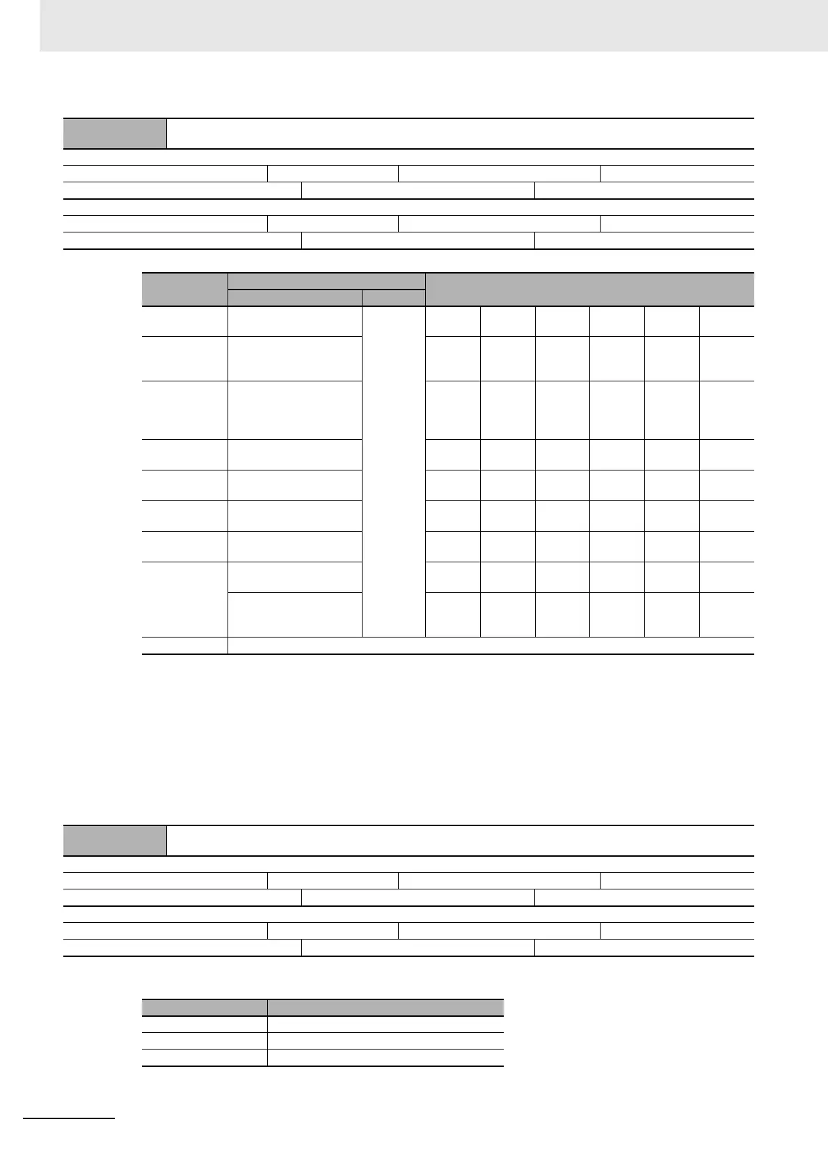
No_01 ... 30 Display Mode
Subindex 0: Number of Entries
Range: 01 hex Unit: --- Default: 01 hex Attribute: ---
Size: 1 byte (U8) Access: RO PDO map: Not possible
Subindex 1: No_01 ... 30 Display Mode
Range: 00000000 to 0001FFFF hex Unit: --- Default: --- hex Attribute: A
Size: 4 bytes (U32) Access: RW PDO map: Not possible
Data
Setting
Target Sensor Amplifier
Y = 0 Y = 1
000Y0000 hex Threshold
level/detection level [Std]
Solution
Viewer (*)
FA□0
MA0
LA0
FAH0
SA0
EA□0
CA0
AA□0VA□0
-
VD□0
000Y0001 hex Margin in detection level
with respect to the
threshold level [PEr]
FA□0
MA0
LA0
FAH0
SA0
EA□0
-
--
-
-
000Y0002 hex The smallest peak value
of incident light and the
largest bottom value of
interrupted light [P-b]
FA□0
MA0
LA0
FAH0
SA0
EA□0
-
AA□0VA□0
-
VD□0
000Y0003 hex Bar graph display [bAr] FA□0
MA0
LA0
FAH0
SA0
EA□0
-
--
-
-
000Y0004 hex Detection level at peak
[PEAK]
FA□0
MA0
LA0
FAH0
SA0
EA□0
-
--
-
VD□0
000Y0005 hex Channel number and
detection level [ch]
FA□0
MA0
LA0
FA
H0
SA0
EA
□0
CA0
AA□0VA□0
-
-
000Y0007 hex Change finder [CFdr] FA□0
MA0
LA0
FAH0
-
-
-
--
-
-
000Y0008 hex RGB display [rGb] -
-
-
-
-
-
CA0
--
-
-
Ch1 detection level or
Ch2 detection level
display [dGdG]
-
MA0
-
-
-
-
-
--
-
-
Other values Not used.
4013 + (N-1) × 80
hex
No_01 ... 30 Inverted Display
Subindex 0: Number of Entries
Range: 01 hex Unit: --- Default: 01 hex Attribute: ---
Size: 1 byte (U8) Access: RO PDO map: Not possible
Subindex 1: No_01 ... 30 Inverted Display
Range: 0000 to FFFF hex Unit: --- Default: --- hex Attribute: A
Size: 2 bytes (U16) Access: RW PDO map: Not possible
Data Setting
0000 hex Inverted display OFF
0001 hex Inverted display ON
0002 to FFFF hex Not used.
 Loading...