Maintenance
4
dpc
%n
hs
500
stnd
500
4000
shs
125
dpc
%ff
----
9999
MODE
MODE
MODE
2.
Detection Function
Changing Light Level and Response Time
per
%ff
per
%n
3. DPC Function
Stable Detection Regardless of Incident (Two outputs are displayed)
Light Level Change
4. Timer Function
Setting Output Timer (Two outputs are displayed)
UP/DOWN
UP/DOWN
13.
Inverted Display *2
Mounting Amplifier in Inverted Direction
12. Digital Display
*2
Changing Digital Display in RUN Mode for Specific Purpose
6.
BANK Switching
Set values are saved for each configured bank.
8.
Percentage Tuning
Detecting Transparent or Microscopic object (Two outputs are displayed)
MODE
MODE
MODE
MODE
MODE
%ff
B
UP/DOWN
UP/DOWN
UP/DOWN
UP/DOWN
(IncidentLightLevelExample)
Detailed Settings
5
dflt
MODE
1. Function Selection
Enabling 6 to 16
ec%
%ff
ec%
%n
UP/DOWN
husr
37
37
UP/DOWN
14.
Eco Function *2
Saving Power Consumption
MovetoDetectionModebyholdingthebuttonfor3secondsorlonger.
15.
Hysteresis width
5.
Power Tuning Level
Changing the Target Incident Light Level (Power Tuning Level)
%n-d
10
10
----
std
A
A
UP/DOWN
UP/DOWN
2
3
4
Select [Setting Mode] -> [Digital Display] to set [diSP CFdr].
Pressing the [MODE] button for 3 seconds or longer exits the SET mode.
Before Passing Right after passing
Let the workpiece pass.
Displays and retains the light intensity (maximum/minimum value) in white digital for 0.5 seconds when the workpiece passes.
1.
2.
3.
4.
0
2000
Hold both for 3 sec. or longer Hold both for 3 sec. or longer
6000
4000
2000
9999
2000
1000
Enable Cancel
Convenient Setting Features
3
For Stable Detection Regardless of Received Light Intensity Changed due to Dust or Dirt
●Zero Reset Function
Returning Received Light Intensity Display to "0"
●
Change finder
Checking Received Light Intensity When Workpiece Passes at High Speed
E3NX-MA□□Series
Thethresholdalsochangesaccordingly.
The lower threshold limit is -1999.
hstd
STND Standard Mode
(a)
Off-delay Timer
Time Off
(b)
On-delay Timer
(c)
One shot
(d)
On Off-delay Timer
DPC ON
SHS Super High-speed ModeGIGA Giga Power Mode
HS
High-speed
Mode
DPC OFF
%n
ptun
MODE
7.
Power Tuning ON/OFF Setting
To Turn ON/OFF the Light Amount Adjustment at Tuning
UP/DOWN
Powertuning
adjustmentON
PercentagetuningON
Percentage
tuningOFF
std
9.
Output 1 Mode
Output mode for the output 1 is changed.
UP/DOWN
Normal
detectionmode
Basicsetting
Detailedsetting
Threshold
/Receiving
light amount
Normal
Reverse
Ecofunction
OFF
EcofunctionON
EcofunctionLO
Standard
setting
Usersetting
fd
f
MODE
BANK1
BANK2 BANK3 BANK4
ban
B
MODE
T
T
T
T
Off-delay Timer
Holds the output ON for
detection by PLC when
the detection time is too
short.
On-delay Timer
Delays the output ON
after detection.
No Incident Light
Incident Light
No Incident Light
Incident Light
No Incident Light
Incident Light
No Incident Light
Incident Light
ON
OFF
ON
OFF
L-ON
D-ON
ON
OFF
ON
OFF
L-ON
D-ON
Tb
Ta
Tb
ON
OFF
ON
OFF
L-ON
D-ON
Ta
(a)
(b)
One-shot Timer
Keeps the output ON for
a specified time regardless
of the workpiece size
variations.
T
T
ON
OFF
ON
OFF
L-ON
D-ON
(c)
ON/OFF-delay Timer
Sets both OFF-delay Timer
and On-delay Timer.
(d)
ban
ban ban
The display reverses.
Threshold and light intensity are displayed on
green digital and white digital respectively.
The OUT Selection Indicators show items
for Output1/Output 2 individually for each output.
The DPC indicator turns ON
when the DPC function is
effective.
●DPC Function
Time
内部受光量
Internal Incident Light Level
Incident Light
Level
Displayed Incident Light Level
Threshold
Level
Stabilizes the displayed
incident level by
correcting internal
incident level changes.
Smart
Tuning
SET
mode
Run Select
DPC Function
ON
Refer to "
②
Settings".
Ratings and Specifications
4-2
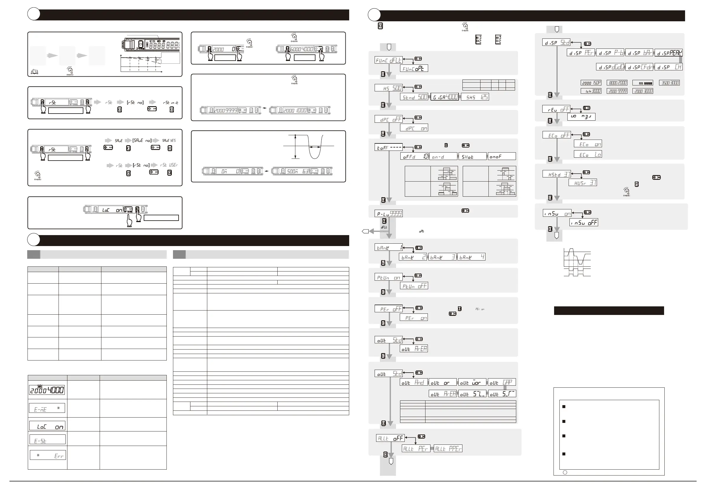
Hold button for 3 seconds or longer to enter SET mode.
MODE
SET mode provides the following function settings. The initial
display shown after transition from one function to another
represents the factory default.
UP/DOWN
Use button to set the power tuning level.
(100 to 9999 in 1 steps; the initial value: 9999)
UP/DOWN
Use button to set the time.
Function Selection: [ ]
Function Selection: [ ]
Press button in [ ] menu, then use
button to set the percentage tuning level.
(-99% to 99% in 1% steps; the initial value: -6%)
MODE
UP/DOWN
func
func
Detectionfunction
Responsetime
Lightquantity
HS
450μs 1ms 16ms 100μs
1(reference)
STND
x1
GIGA
x8
SHS
x0.25
Besuretocheckthestabilityofoutputs
asthereisapossibilityofchattering.
Thehysteresiswidthcanbesetbypressingthebuttoninthemenu
of"husr"andthenpressingthebutton.(0to9999,incrementsof1)
MODE
UP/DOWN
UseoftheDPCfunctionwiththrough-beammodel
orregressivereflectionmodelisrecommended.
MODE
After pressing the button,
Whensmarttuningisinerror/
maximumsensitivitytuningisexecuted/
the1stpointofthepositiontuningissmaller/area
detectionmode,theDPCfunctionisdisabled.
(Referencevalue)
ec%
l%
Ecoon
The indicators (green digital and white digital) turn OFF.
They turn ON for approx. 10 seconds and then turn OFF
by button operation.
Eco Lo
They turn ON for approx. 10 seconds and then
the indicators (All) turn ON
with low brightness.
h
Suitability for Use
s
Omron Companies shall not be responsible for conformity with any standards,
codes or regulations which apply to the combination of the Product in the
Buyer’s application or use of the Product. At Buyer’s request, Omron will
provide applicable third party certification documents identifying ratings and
limitations of use which apply to the Product. This information by itself is not
sufficient for a complete determination of the suitability of the Product in
combination with the end product, machine, system, or other application or
use. Buyer shall be solely responsible for determining appropriateness of the
particular Product with respect to Buyer’s application, product or system.
Buyer shall take application responsibility in all cases.
NEVER USE THE PRODUCT FOR AN APPLICATION INVOLVING
SERIOUS RISK TO LIFE OR PROPERTY WITHOUT ENSURING THAT THE
SYSTEM AS A WHOLE HAS BEEN DESIGNED TO ADDRESS THE RISKS,
AND THAT THE OMRON PRODUCT(S) IS PROPERLY RATED AND
INSTALLED FOR THE INTENDED USE WITHIN THE OVERALL
EQUIPMENT OR SYSTEM.
See also Product catalog for Warranty and Limitation of Liability.
Oct, 2014
D
OMRON Corporation
Industrial Automation Company
Contact: www.ia.omron.com
Tokyo, JAPAN
OMRON ELECTRONICS LLC
2895 Greenspoint Parkway, Suite 200
Hoffman Estates, IL 60169 U.S.A.
Tel: (1) 847-843-7900/Fax: (1) 847-843-7787
OMRON ASIA PACIFIC PTE. LTD.
No. 438A Alexandra Road # 05-05/08 (Lobby 2),
Alexandra Technopark,
Singapore 119967
Tel: (65) 6835-3011/Fax: (65) 6835-2711
OMRON (CHINA) CO., LTD.
Room 2211, Bank of China Tower,
200 Yin Cheng Zhong Road,
PuDong New Area, Shanghai, 200120, China
Tel: (86) 21-5037-2222/Fax: (86) 21-5037-2200
OMRON EUROPE B.V.
Sensor Business Unit
Carl-Benz-Str. 4, D-71154 Nufringen, Germany
Tel: (49) 7032-811-0/Fax: (49) 7032-811-199
Regional Headquarters
Thechangefinderisnot
displayedin[SettingMode].
Iftheproductisthereflective
type,thelocalmaximumvalueis
displayedbysettinglight-on.Ifit
isthethrough-beamtype,the
localminimumvalueisdisplayed
bysettingdark-on.
ptun
%ff
PowertuningadjustmentOFF
area
Areadetectionmode*1
(Two outputs are displayed)
Set the hysteresis width by initial value. Hysteresis width is
provided for threshold to prevent the judgment output from
becoming unstable near the boundaries.
(1 to 9999ms in 1ms steps; the initial value: 10ms
Errorrange
:
0.1ms
)
●
Troubleshooting
Problem Cause Remedy
Remedy
Cause
Error Name / Display
●
Error Display
2000
4000
Troubleshooting
4-1
DPC Error
*1
Turn ON the power again. Reset the settings
if the error is not corrected.
*
3
If the error remains, the error is caused by
memory failure such as rewrite count
exceeded. Please replace the amplifier unit.
Load short circuit detection error
Lock ON
*2
Refer to "
⑤
Detailed Settings".
Cancel the key lock function.
*3
Check wiring and connector connection
again.
*4
Failed internal data
read/out
The key lock
function enabled
Over current flowing
to the control output
*4
Refer to "
③
Convenient Setting Features"
*1
Refer to "1-2 Input/Output Circuit Diagram"
*3
Refer to "1-3 Mounting Amplifier Unit"
*2
Refer to "2-3 Smart Tuning "
*4
Refer to "1-2 Input/Output Circuit Diagram"
and "4-2 Ratings and Specifications"
*1
The DPC indicator blinks.
*3
Refer to "
③
Convenient Setting Features"
e-st
Check the wiring, connector connection, power supply
voltage and power supply capacity again.
*1
Nothing is shown
on the indication.
No power supplied or the
cable broken
Turn OFF Eco mode.
*2
Nothing is shown on
the digital indication.
Eco mode is ON.
Check the Amplifier Units mounted in a group and
turn ON the power again.
*3
The OUT indicator
blinking
Mutual interference or
other reason
Cancel the zero reset function.
*4
Incident light level displayed
in a negative value
The zero reset function is
enabled.
The light intensity
level display changes.
Affected by dust or dirt, temperature
change, vibration, etc.
Reset the settings.
*4
Lost tracking of
the settings made
ー
Setting GIGA Mode increases emission
power and light intensity.
*2
Sensing/Detection
not possible
despite the
minimum threshold
level
Detection set to a small
light level mode Dust or
dirt influences
Wipe the dust off the Fiber Unit detection
surface or other relevant areas and recover
the original incident light level. Then, perform
Smart Tuning.
*2
The incident light level
has deteriorated due
to dust or dirt.
EEPROM error
(Two outputs are displayed)
(Two outputs are displayed)
150p
(a)
2000
8000
(b)
(c)
3000
3500
(d)
3000
(e)
9999
2000
(f)
Threshold
Received light intensity ratio Peak receiving light amount
Bottom receiving light amount
Threshold
120% 100% 80%
Peak receiving light amount
Receiving light amount
CH number
Receiving light amount
Threshold
Received light amount after passing
3000
2000
(g)
OUT1 receiving light amount OUT2 receiving light amount
p-b
bar
(a)Toseethereserveofthelight
intensitylevelforthethreshold
(b)Tosetthethresholdwitha
microscopicobjectorfast-movingobject
(c)Toseetheintuitiveand
easytofollowdisplay
(d)Toadjustthebeam
per
(f)Toseethereceivedlightintensity
whenworkpiecepassesathighspeed
cfdr
(e)ToknowtheCHnumberwhentwo
ormoreunitsconnected
ch
(g)Toseethereceivedlightintensityof
OUT1andOUT2simultaneously
dgdg
Press both the [MODE] and [L/D] buttons for at least 3 seconds
to set to [SoLU on]. To release the setting, press the [MODE]
and [L/D] buttons for at least 3 seconds to set to [SoLU oFF].
Let the workpiece pass.
Passing time and light amount difference are displayed.
1.
2.
3.
Press the [MODE] and [L/D] buttons at the same time
for at least 3 seconds to exit setting mode.
4.
LightamountdifferencePassingtime
(m:msec,μ:μsec)
LightamountdifferencePassingtime
(m:msec,μ:μsec)
0m
0
500m
63
Enable/Cancel
(The same procedure)
rst
●
Solution Viewer
Determining If Workpiece is Detectable
●Setting Reset
Initializing Settings
rst
●Key Lock Function
Preventing Malfunction
●User Save Function/User Reset Function
Saving/Reading Settings
Initialize all settings to the factory-set defaults.
Disables all the button operations.
* Press either of UP/DOWN.
Hold both for 3 sec. or longer
Hold both for 3 sec. or longer
Hold both for 3 sec. or longer
Lightamountdifference
Threshold
Passingtime
(msorμs)
[rst]
MODE MODE
[ ]
UP/DOWN
[rst]
[rst user
]
yes
MODE MODE
UP/DOWN
[ ] [ ]
UP/DOWN
UP/DOWN
MODE
MODE
User Save Function
User Reset Function
e-me
*
MODE
A
When executing the DPC function or
smart tuning, zero resetting is cancelled.
"Enable/disable" of zero resetting and
the zero resetting value can be saved
for each bank.
User Resetting and User Saving are applicable to the bank
common setting only.
The receiving light intensity display is
stabilized using the DPC function.*4
Theasterisk*representsanumber.
In the sensor OFF or emission OFF state, setting
initialization and user resetting are disabled. Cancel
the sensor OFF or emission OFF state before trying
again.
While writing in the EEPROM, setting initialization
and user resetting are disabled. Wait for a couple of
seconds and try again.
Setting change or
writing to the
EEPROM are
disabled.
Settingchangeexecutionerror
*isinitorUSEr
err
*
*1. The relationship between the control output and output switch during area detection mode is as follows:
Hi
Lo
ON
OFF
ON
OFF
Light ON
Control output
Light ON
Control output
*2. It is a common setting for BANK. Only one set value can be set between BANK1 to BANK4.
%n
UP/DOWN
16. Writing to EEPROM *2
ON
OFF
Turning ON/OFF of the setting change save by batch tuning
When "oFF" is displayed, the settings changed by external input or
batch tuning are not written to the EEPROM, preventing it from
reaching the end of its life (writing 1000000 times).
MODE
11.
Batch tuning setting*2
Tuning multiple amplifiers together
MODE
allt
UP/DOWN
Batchpercenttuning Batchpowerpercenttuning
per
allt
BatchtuningfunctionOFF
If others than oFF is selected, the percentage tuning setting display remains.
pper
allt
std
10.
Output 2 Mode
Output mode for the output 2 is changed.
UP/DOWN
Normal
detectionmode
and
ANDoutputmode ORoutputmode XORoutputmode
gap
GAPoutputmode
Fallingsynchronizationmode Risingsynchronizationmode
OutputswiththeconditioninwhichbothOutput1andOutput2areturnedON.
OutputswiththeconditioninwhicheitheroneofOutput1orOutput2isturnedON.
Output1andoutput2areONindifferentconditions.
Theproductoperatesbythedifferencevalueof(output1receivinglightamount)-
(output2receivinglightamount).Alljudgmentofthresholdvalueoroutputisalso
executedforthedifferencevalue.Thelowerlimitofthresholdvalueis-1999.
Risingsynchronization.Outputifoutput1isONwhenoutput2changesfromOFFtoON
Fallingsynchronization.Outputifoutput1isONwhenoutput2changesfromONtoOFF
ANDoutputmode
ORoutputmode
XORoutputmode
GAPoutputmode
Risingsynchronizationmode
Fallingsynchronizationmode
area
Areadetectionmode
*1
Approx.60g/Approx.20g
-
Model
NPNoutput
PNPoutput
E3NX-MA6
E3NX-MA8
Wire-savingconnector
Cablelength2m
Cablelength5m
Controloutput
Connectionmethod
Lightsource(Wavelength)
Powersupplyvoltage
Powerconsumption*1
Controloutput
Protectioncircuit
MaximumconnectableUnits
Numberofunitsformutual
interferenceprevention
*2
BankSwitchSetting
AutoPowerControl(APC)
Ambientillumination
Surrounding
airTemperaturerange
*3
Ambienthumidityrange
Altitude
Installationenvironment
Insulationresistance
Dielectricstrength
Vibrationresistance
Shockresistance
Weight
(packedstate/sensor)
Materials
E3NX-MA11
E3NX-MA41
2*3
Pre-wired
Red4-elementLED(625nm)
10to30VDC,includingripple(p-p)10%
Powersupplyvoltage24V:
Normalmode:960mWmax.(Currentconsumption40mAmax.)
EcofunctionON:770mWmax.(Currentconsumption32mAmax.)
EcofunctionLO:870mWmax.(Currentconsumptionat36mAmax.)
Loadpowersupplyvoltage:30VDC,opencollectoroutputtype(dependsontheNPN/PNPoutputformat)
Loadcurrent:100mAmax.for1to3unitsuse,20mAmax.for4ormoreunitsconnected
Residualvoltage:Loadcurrentlessthan10mA:1Vmax.,loadcurrent10to100mA:2Vmax.
Off-statecurrent:0.1mAmax.
Powersupplyreversepolarityprotection,outputshort-circuitprotectionandoutputincorrectconnectionprotection
30units
9units Note:Thecommunicationandmutualinterferencepreventionfunctionsaredisabled
ifSuperHighSpeedmode(SHS)isselectedfordetectionfunction.
SelectablefromBANK1-4
Provided(Alwayseffective)
IlluminationintensityIncandescentlamp:20,000lxmax./Sunlight:30,000lxmax.
Operating:1to2amplifiersconnected:−25℃to55℃,3to10amplifiersconnected:−25℃to50℃,
11to16amplifiersconnected:−25
℃
to45
℃
,17to30amplifiersconnected:−25
℃
to40
℃
Storage:−30
℃
to70
℃
(withnoicingorcondensation)
Operatingandstorage:35to85%(withnocondensation)withinthesurroundingairtemperaturerangeshownabove
2000mmax.
Pollutiondegree3(asperIEC60947-1)
20MΩmin.(at500VDC)
1,000VAC,50/60Hz,1minute
10to55Hzwitha1.5mmdoubleamplitudefor2hrseachinX,YandZdirections
500m/s
2
,for3timeseachinX,YandZdirections
Approx.115g/Approx.75g
Approx.200g/Approx.160g
Caseandcover:Polycarbonate(PC),Cable:PVC
*1.Powerconsumption
Powersupplyvoltage10Vto30V:
Normalmode:1080mWmax.(Powersupplyvoltage30V:Currentconsumption36mAmax./
Powersupplyvoltage10V:Currentconsumption75mAmax.)
EcofunctionON:840mWmax.(Powersupplyvoltage30V:Currentconsumption28mAmax./
Powersupplyvoltage10V:Currentconsumption55mAmax.)
EcofunctionLO:960mWmax.(Powersupplyvoltage30V:Currentconsumption32mAmax./
Powersupplyvoltage10V:Currentconsumption65mAmax.)
*2.
Thetuningwillnotchangethenumberofunits.
TheleastunitcountamongthemutualinterferencepreventionunitsofE3NXandE3NC.
Checkthemutualinterferencepreventionunitcountandresponsespeedofeachmodel.
*3.
Whenthenumberofconnectedunitsis11ormore,theambienttemperatureislessthan50℃.
MODE
Light intensity

 Loading...