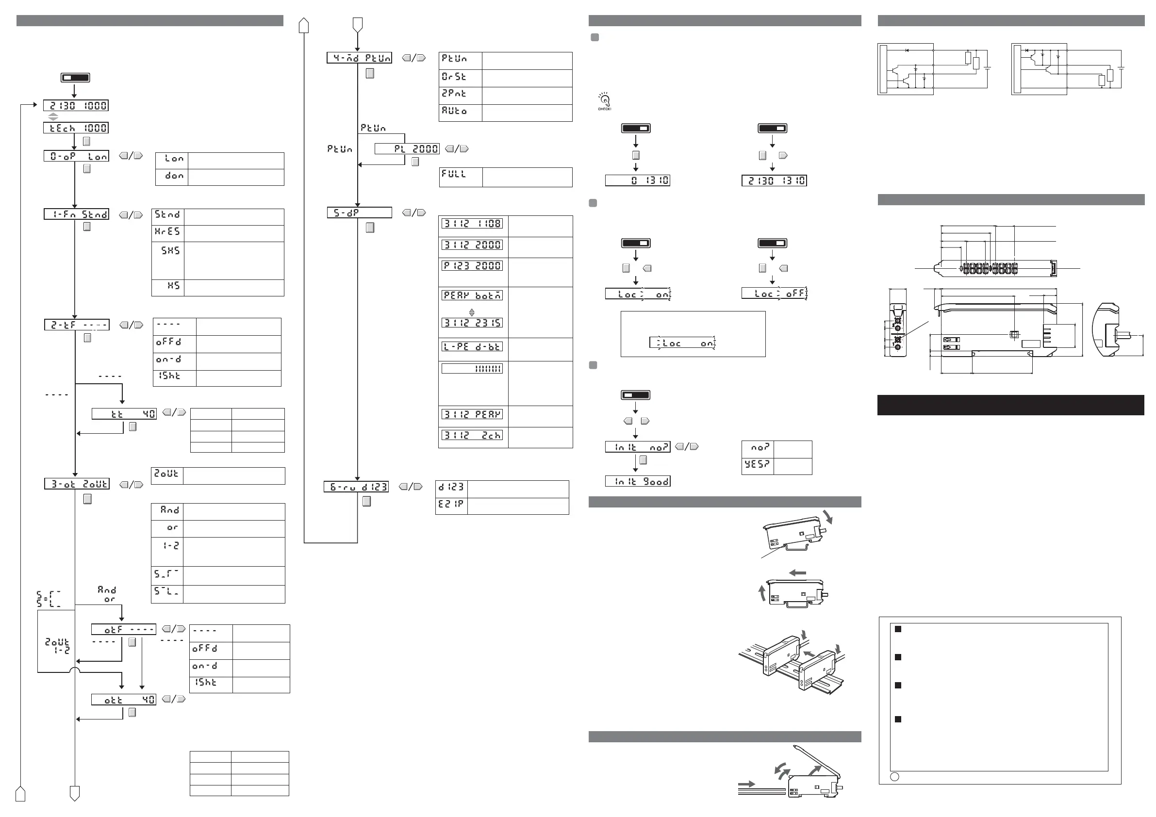
RUNSET
Teaching (Light level/Threshold display)
0. Operation
Mode
Light-ON
LON
DON
Dark-ON
1-ms increments1 to 20 ms
5-ms increments
20 to 200 ms
100-ms increments200 ms to 1 s
1-s increments1 to 5 s
Timer disabled.
----
OFF D
OFF-delay timer
ON-D
ON-delay timer
1SHT
One-shot timer
Switch to SET mode.
Setting range: 1 to 5,000
Not
1. Detection
Method
Set separately for each channel.
Set separately for each channel.
2. Timer
Timer Time
Not
Note: Refer to 4. Basic Settings for teaching methods.
The following functions can be set in SET mode. The default settings are shown in the transition boxes
between functions.
All settings except for the operation mode and timer settings are the same for both channels.
*: The values shown for thresholds, incident light levels, percentages, etc., are examples only. Actual
displays may vary.
Normal display
D123
321D
Reversed display
Tunes the power.
Teaching With and Without a
Workpiece
Automatic-teaching
Maximum power
B
PTUN
0RST
FULL
Executes a zero reset.
2PNT
AUTO
Setting range: 100 to 3,900
The function of the MODE key in RUN mode can be selected.
4. MODE Key
Setting
If the output setting is set to 1-2 (differential operation),
channel 2 cannot be zeroed.
The incident light level displayed on the main display can be zeroed. The threshold displayed in the
sub-display is shifted by an amount corresponding to the amount the incident light level was
changed.
Confirm that the MODE key setting is 0RST (zero reset) in advance. PTUN (power tuning) is the
default setting. Refer to 5. Detailed Settings.
Select the channel for zeroing with the channel selector.
■ Setting Method ■ Clearing Method
All key operations can be disabled to help prevent key operating errors.
Only the operation keys are disabled. The switches and selectors will still function.
■ Setting Method ■ Clearing Method
This procedure can be used to return all the settings to the original default values.
■ Setting Method
■ Mounting Units
Catch the hook on the Fiber Unit connector end of the
Unit on the DIN Track and then press down on the
other end of the Unit until it locks into place.
Always attach the Fiber Unit connector end first.
If the incorrect end is attached first, the mounting
strength will be reduced.
■ Removing Units
Press the Unit in the direction indicated by "1"
and then lift up on the Fiber Unit connector end
of the Unit in the direction indicated by "2."
■ Joining Amplifier Units (for Units with Connectors)
Up to 16 Units can be joined.
1. Mount the Amplifier Units one at a time onto the
DIN Track.
2. Slide the Amplifier Units together and press the
Amplifier Units together until they click into place.
Secure the Units with an End Plate (PFP-M) if there is a
possibility of the Amplifier Units moving, e.g., due to vibration.
Reverse the above procedure to separate and remove the
Units. Do not attempt to remove Amplifier Units from the
DIN Track without separating them first.
1. Open the protective cover
2. Press up the lock button.
3. Insert the fibers all the way to the back
of the connector insertion opening.
4. Return the lock button to its original
position to secure the fibers.
Zeroing the Main Display
Switch to RUN mode.
Switch to RUN mode.
Switch to RUN mode. Switch to RUN mode.
The display will be zeroed,
i.e., the incident light level
will be displayed as 0.
RUNSET RUNSET
RUNSET
Press the MODE key for
at least 3 seconds.
The display of the incident light
level will stop changing.
Initializing Settings
RUNSET
RUNSET
Initialization has been completed.
Key Lock
Settings not
initialized.
NO?
YES?
Settings
initialized.
Switch to SET mode.
+
+
+
Press the UP and DOWN key together for at least 3 seconds.
+
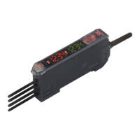
Channel 1 light level Channel 2 light level
Channel 1 light level Channel 2 light level
LOC ON
LOC OFF
INIT Press the MODE key at the
NO? or YES? display.
INIT GOOD
Hold down the MODE key and
press the DOWN key for at
least 3 seconds.
Press the DOWN key right
after pressing the MODE key.
The zero reset
function will be
cleared.
Hold down the MODE key and
press the UP key for at least 3
seconds. Press the UP key right
after pressing the MODE key.
The sub-display will flash
twice and key input will be
disabled.
Hold down the MODE key
and press the UP key for at
least 3 seconds. Press the
UP key right after pressing
the MODE key.
The sub-display will
flash twice and key
input will be enabled.
1
1
2
DIN Track
1
2
DIN Track
Hook on the Fiber Unit connector end
1
2
4
3
If a key is pressed while key operations are locked,
"LOC ON" will flash twice on the display to indicate
that key operations have been disabled.
Reverse the above procedure to disconnect the Fiber Unit.
3. Output
Setting
Light level PEAK
Light level Channel
The incident light level
and the channel.
Light level Threshold
The information displayed in RUN mode can be selected.
When going to SET mode, this setting will be ignored and
the incident light level and threshold value will be displayed.
5. Display
Switch
% light level
Threshold
L-PE D-BT
Detection status
Alternates at
a fixed interval
PEAK BOTM
Peak level
Bottom level
Standard mode
Response Time:1ms
STND
HRES
High-resolution mode:
Response Time:4ms
SHS
Super-high-speed mode
Response time: 130
μ
s
(200
μ
s when AND, OR, leading edge
sync,falling edge sync, or differ-ential
output is enabled)
HS
High-speed mode
Response time:450μs
A
The current incident
light level and the peak
incident light level.
The incident light level
and threshold value
The incident light level
as a percentage of the
threshold value and the
threshold value.
The peak incident level
and bottom incident level
of fixed time(2s).
The incidient light peak
level and no incident
light bottom level.
Analog bar display. The
current detection status
is displayed as an
analog bar. The bar will
lengthen from the right
as ON status is reached.
6. Display
Orientation
5. Detailed Settings 6. Convenient Functions 9. I/O Circuits
10. Dimensions
7. Installing the Amplifier Unit
8. Connecting the Fiber Unit
The operation of channel 2 output can be selected.
The settings described below apply to channel 2 output.
(Channel 1 output is not affected.)
Output for each channel
2OUT
And
Output when the output is ON for both
channels 1 and 2.
or
Output when the output is ON for
either channel 1 or channel 2.
1-2
Rising edge sync. Output if channel 1 is ON when
channel 2 changes from OFF to ON.
Falling edge sync. Output if channel 1 is ON when
channel 2 changes from ON to OFF.
Internal circuits
Load
Load
12 to
24 VDC
Brown
Channel
1 output
Blue
Internal circuits
Load
Load
12 to
24 VDC
Brown
Black
Orange
Blue
Channel
2 output
Black
Orange
■ NPN Models ■ PNP Models
Channel
2 output
Channel
1 output
Channel 1 light level Channel 2 light level
The incident light levels
for channels 1 and 2.
A display is changed in fixed time.
Suitability for Use
THE PRODUCTS CONTAINED IN THIS SHEET ARE NOT SAFETY RATED.
THEY ARE NOT DESIGNED OR RATED FOR ENSURING SAFETY OF
PERSONS, AND SHOULD NOT BE RELIED UPON AS A SAFETY
COMPONENT OR PROTECTIVE DEVICE FOR SUCH PURPOSES.
Please refer to separate catalogs for OMRON's safety rated products.
OMRON shall not be responsible for conformity with any standards, codes, or
regulations that apply to the combination of the products in the customer's
application or use of the product.
Take all necessary steps to determine the suitability of the product for the
systems, machines, and equipment with which it will be used.
Know and observe all prohibitions of use applicable to this product.
NEVER USE THE PRODUCTS FOR AN APPLICATION INVOLVING
SERIOUS RISK TO LIFE OR PROPERTY WITHOUT ENSURING THAT THE
SYSTEM AS A WHOLE HAS BEEN DESIGNED TO ADDRESS THE RISKS,
AND THAT THE OMRON PRODUCT IS PROPERLY RATED AND
INSTALLED FOR THE INTENDED USE WITHIN THE OVERALL
EQUIPMENT OR SYSTEM.
See also Product catalog for Warranty and Limitation of Liability.
OMRON Corporation
EUROPE
OMRON EUROPE B.V. Sensor Business Unit
Carl-Benz Str.4, D-71154 Nufringen Germany
Phone:49-7032-811-0 Fax: 49-7032-811-199
NORTH AMERICA
OMRON ELECTRONICS LLC
One Commerce Drive Schaumburg,IL 60173-5302 U.S.A.
Phone:1-847-843-7900 Fax : 1-847-843-7787
ASIA-PACIFIC
OMRON ASIA PACIFIC PTE. LTD.
No. 438A Alexandra Road #05-05-08(Lobby 2),
Alexandra Technopark, Singapore 119967
Phone : 65-6835-3011 Fax :65-6835-2711
o
CHINA
OMRON(CHINA) CO., LTD.
Room 2211, Bank of China Tower,
200 Yin Cheng Zhong Road,
PuDong New Area, Shanghai, 200120, China
Phone : 86-21-5037-2222 Fax :86-21-5037-2200
OCT, 2009
A
B
1-ms increments1 to 20 ms
5-ms increments20 to 200 ms
100-ms increments200 ms to 1 s
1-s increments1 to 5 s
Timer disabled
----
OFFD
OFF delay timer
ON-D
ON delay timer
1SHT
One-shot timer
Setting range: 1 to 5,000
Not
The timer for the output of either AND or OR
can be set, depending on which is selected.
Timer time
Timer
Note 1: When rising edge sync or falling edge sync is
selected, the one-shot timer is automatically set,
i.e., the timer function cannot be selected.
2: Set the timer for channel 2 output or differential
output (1-2) using the normal timer setting (2-tF)
for channel 2.
Operates according to the difference
between channels (channel 1 - channel 2).
The difference is used for both threshold
and output judgement execution.
LOC ON
12.50
11.703.9×3=
32.80
29.80
11.703.9×3=
15.10
12.15
14
36.70
3.40
70
8.10
18.70
32
4.30
9.90
44.30
4.50
7
4.50
5.65
10
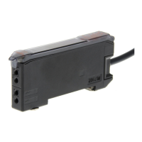
(Prewired Models)
Four, 2.40 dia.
(Unit: mm)
 Loading...