E3Z-L
I/O Circuit Diagrams
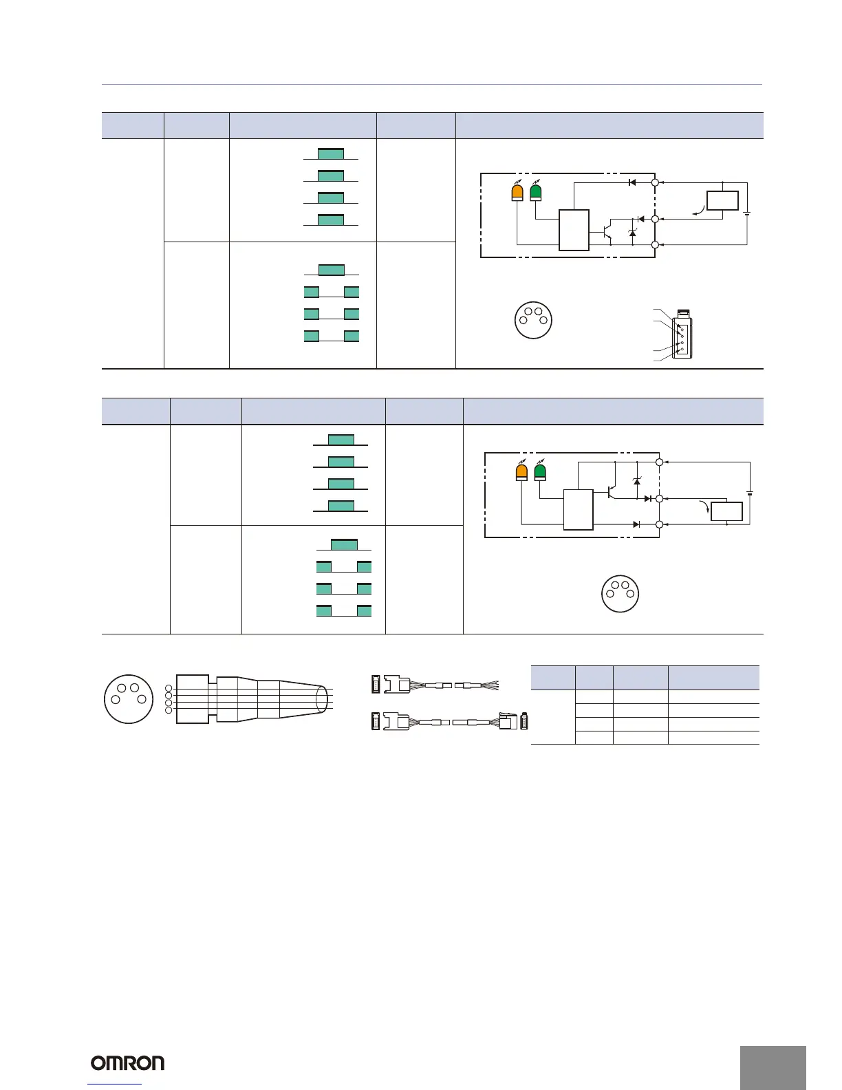
NPN Output
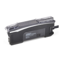
PNP Output
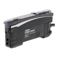
Plugs (Sensor I/O Connectors)
Model
Operation
mode
Timing charts
Operation
selector
Output circuit
E3Z-L61
E3Z-L66
Light-ON
L side
(LIGHT ON)
Dark-ON
D side
(DARK ON)
Incident light
No incident light
ON
OFF
ON
OFF
Operate
Reset
Operation
indicator
(orange)
(Between brown and black leads)
Output
transistor
Load
(e.g., relay)
Narrow-beam Reflective Models
Connector Pin Arrangement
Pin 2 is not used.
4
1
2
4
3
3
1
12 to 24 VDC
Brown
Black
Control output
Blue
100 mA
max.
Operation
indicator
Stability
indicator
GreenOrange
0 V
Z
D
Load
(Relay)
Photo-
electric
Sensor
Main
Circuit
e-CON Connector Pin Arrangement
1
2
3
4
Incident light
No incident light
ON
OFF
ON
OFF
Operate
Reset
Operation
indicator
(orange)
(Between brown and black leads)
Output
transistor
Load
(e.g., relay)
Model
Operation
mode
Timing charts
Operation
selector
Output connector
E3Z-L81
E3Z-L86
Light-ON
L side
(LIGHT ON)
Dark-ON
D side
(DARK ON)
Incident light
No incident light
OFF
ON
OFF
Operate
Reset
Operation
indicator
(orange)
(Between brown and black leads)
Output
transistor
Load
(e.g., relay)
Narrow-beam Reflective Models
Connector Pin Arrangement
Pin 2 is not used.
4
1
2
4
3
1
3
12 to 24 VDC
Brown
Black
Blue
100 mA
max.
Control output
Operation
indicator
Stability
indicator
GreenOrange
0 V
Z
D
Load
(Relay)
Photo-
electric
Sensor
Main
Circuit
Incident light
No incident light
ON
OFF
ON
OFF
Operation
indicator
(orange)
(Between brown and black leads)
Output
transistor
Load
(e.g., relay)
Operate
Reset
Note: Pin 2 is not used.
Classifi-
cation
Wire
color
Connector
pin No.
Application
DC
Brown 1 Power supply (+V)
White 2 ---
Blue 3 Power supply (0 V)
Black 4 Output
2
4
1
3
1
2
3
4
Brow