Photoelectric Sensors Technical Guide
● Design
Power Reset Time
The Sensor will be ready to detect within approximately 100 ms after
the power is turned ON.
If the Sensor and the load are connected to separate power supplies,
turn ON the Sensor power before turning ON the load power. Any
exceptions to this rule are indicated in Safety Precautions in individual
product information.
Turning OFF Power
An output pulse may be generated when the power is turned OFF. It
is recommended that the load or load line power be turned OFF
before the Sensor power is turned OFF.
Power Supply Types
An unsmoothed full-wave or half-wave rectifying power supply cannot
be used.
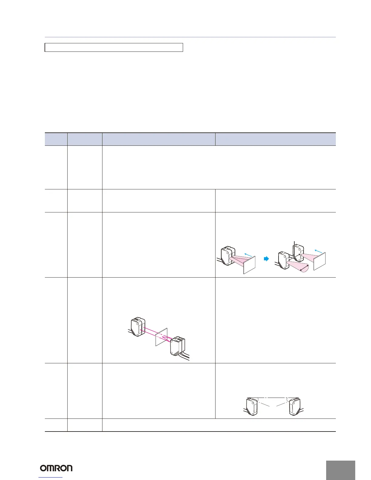
Mutual Interference
Mutual interference is a state where an output is unstable because the Sensors are affected by light from the adjacent Sensors.
The following measures can be taken to avoid mutual interference.
Precautions for Correct Use
Counter-
measure
Concept Through-beam Sensors Reflective Sensors
1
Use a Sensor
with the
interference
prevention
function.
If Sensors are mounted in close proximity, use Sensors with the interference prevention function.
10 or fewer Sensors: E3X-DA@-S, E3X-MDA, E3C-LDA Fiber Sensors
Performance, however, will depend on conditions. Refer to pages E3X-DA-S/E3X-MDA
and E3C-LDA.
5 or fewer Sensors: E3X-NA Fiber Sensors
2 or fewer Sensors: E3T, E3Z, E3ZM, E3ZM-C, E3S-C, E3G-L1/L3, or E3S-C Built-in Amplifier Photoelectric
Sensors (except Through-beam Sensors)
E3C Photoelectric Sensor with separate amplifier
2
Install an
inference
prevention
filter.
A mutual interference prevention polarizing filter can be
installed on only the E3Z-TA to allow close-proximity
mounting of up to 2 Sensors.
Mutual Interference Prevention Polarizing Filter: E39-E11
---
3
Separate
Sensors to
distance where
interference
does not occur.
Check the parallel movement distance range in the
catalog, verify the set distance between adjacent
Sensors, and install the Sensors accordingly at a
distance at least 1.5 times the parallel movement
distance range.
If the workpieces move from far to near, chattering may
occur in the vicinity of the operating point. For this type of
application, separate the Sensors by at least 1.5 times the
operating range.
4
Alternate
Emitters and
Receivers.
Close mounting of Sensors is possible by alternating
the Emitters with the Receivers in a zigzag fashion (up
to two Sensors). However, if the workpieces are close
to the Photoelectric Sensors, light from the adjacent
Emitter may be received and cause the Sensor to
change to the incident light state.
---
5
Offset the
optical axes.
If there is a possibility that light from another Sensor
may enter the Receiver, change the position of the
Emitter and Receiver, place a light barrier between the
Sensors, or take other measures to prevent the light
from entering the Receiver.
(Light may enter even if the Sensors are separated by
more than the sensing distance.)
If Sensors are mounted in opposite each other, slant the
Sensors as shown in the following diagram. (This is
because the Sensors may affect each other and cause
output chattering even if separated by more than the
Sensor sensing distance.)
6
Adjust the
sensitivity.
Lowering the sensitivity will generally help.
L
1.5 × L
Sensor
Sensor
W
or
kpiece
Workpiece
Emitter
Receiver
Receiver
Emitter
Workpiece
Sensor Sensor
θθ
http://www.ia.omron.com/
C-2
(c)Copyright OMRON Corporation 2007 All Rights Reserved.

 Loading...