Digital Temperature Controllers E5EZ 11
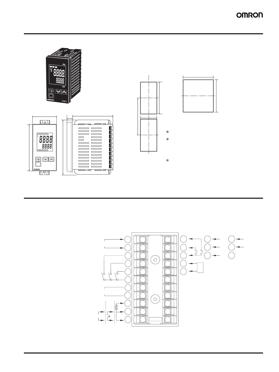
Dimensions
Note: All units are in millimeters unless otherwise indicated.
Wiring Terminals
• The voltage output (control output) is not electrically insulated from the internal circuits. When using a grounding thermocouple, do not connect
the control output terminals to the ground. If the control output terminals are connected to the ground, errors will occur in the measured temper-
ature values as a result of leakage current.
• Standard insulation is applied to the power supply I/O sections. If reinforced insulation is required, connect the input and output terminals to a
device without any exposed current-carrying parts or to a device with standard insulation suitable for the maximum operating voltage of the
power supply I/O section.
120 min
92
+08
0
92
+08
0
45
+08
0
96
ALM1 ALM2 ALM3 HB
OUT1
OUT2
STOP CMW
e
E5EZ
78
112
Recommended panel thickness is 1 to 8 mm.
Group mounting is not possible in the vertical
direction. (Maintain the specified mounting space
between Controllers when they are group
mounted.)
Panel Cutouts
Mounted separately
Group Mounted
(48 × No. of units −2.5)
+10
0
11.5
48
PV
SV
When two or more Controllers are mounted,
make sure that the surrounding temperature does
not exceed the allowable operating temperature
specified in the specifications.
100 to 240 VAC
12
13
14
15
16
2
3
4
5
6
7
8
9
10
11
AL3/OUT2
AL2
OUT1
B
A
B
AL1/HB
CT
EV1
EV2
12
13
14
RS-232C
SD
RD
SG
12
13
14
RS-485
B(+)
A(−)
−
+
TC
Pt
−
+
600 Ω
In
ut
ower su
l
Alarm output, 250 VAC 2 A
resistive load
Voltage output, 12 VDC 40 mV
Current output, 4 to 20 mA DC
Relay output, 250 VAC 5 A
resistive load
Do not use
Analo
in
ut
1
Event inputs
Heater burnout detection input
 Loading...


