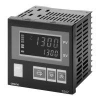
6 Digital Temperature Controllers E5AZ
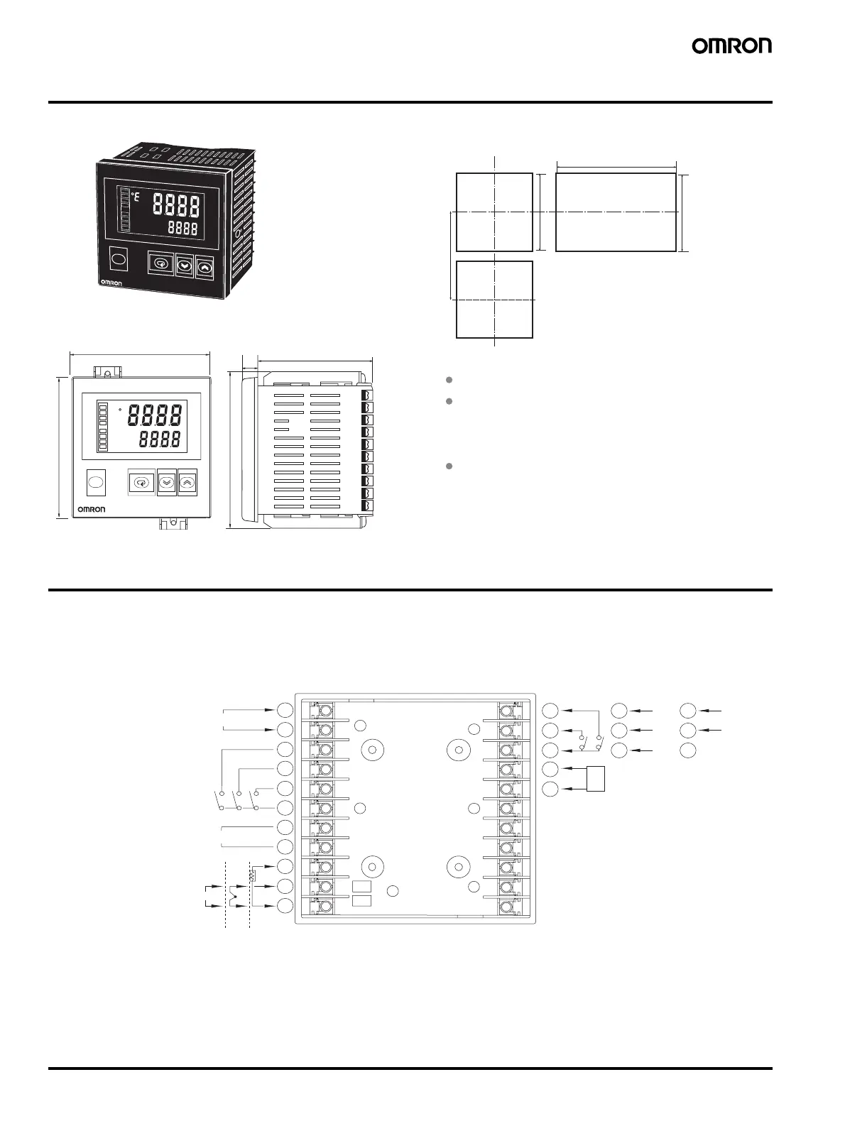
Dimensions
Note: All units are in millimeters unless otherwise indicated.
Wiring Terminals
• The voltage output (control output) is not electrically insulated from the internal circuits. When using a grounding thermocouple, do not connect
the control output terminals to the ground. If the control output terminals are connected to the ground, errors will occur in the measured temper-
ature values as a result of leakage current.
• Standard insulation is applied to the power supply I/O sections. If reinforced insulation is required, connect the input and output terminals to a
device without any exposed current-carrying parts or to a device with standard insulation suitable for the maximum operating voltage of the
power supply I/O section.
120 min
92
+08
0
92
+08
0
92
+08
0
78
11.5
112
96
96
PV
SV
ALM1
ALM2
ALM3
HB
OUT1
OUT2
STOP
CMW
E5AZ
e
E
5
A
Z
P
V
SV
A
L
M
1
A
LM
2
A
L
M
3
H
B
O
U
T1
O
U
T
2
S
T
OP
C
M
W
Recommended panel thickness is 1 to 8 mm.
Group mounting is not possible in the vertica
direction. (Maintain the specified mounting space
between Controllers when they are group
mounted.)
l
When two or more Controllers are mounted,
make sure that the surrounding temperature does
not exceed the allowable operating temperature
specified in the specifications.
Mounted separately
Group Mounted
(96 × No. of units −3.5)
+1.0
0
2
3
4
5
6
7
8
9
10
11
2
3
4
5
6
7
8
9
10
11
12
13
14
15
16
AL3/OUT2
AL2
OUT1
B
A
B
−
+
−
+
12
13
14
15
16
17
18
19
20
21
22
TC
Pt
AL1/HB
CT
EV1
EV2
RS-485
12
13
14
B(+)
A(−)
RS-232C
12
13
14
SD
RD
SG
600 Ω
Do not use
In
ut
ower su
l
Alarm output, 250 VAC 2 A
resistive load
Voltage output, 12 VDC 40 mV
Current output, 4 to 20 mA DC
Relay output, 250 VAC 5 A
resistive load
Analo
in
ut
100 to 240 VAC
1
1
Event inputs
Heater burnout detection input
 Loading...


