EasyManuals Logo

Omron E5CC User Manual

Omron E5CC
440 pages
To Next Page IconTo Next Page
To Previous Page IconTo Previous Page
Page #117 background imageLoading...
Page #117 background image
2 - 79
2 Preparations
E5@C Digital Temperature Controllers User’s Manual (H174)
2-4 Using the Setup Tool Port
2
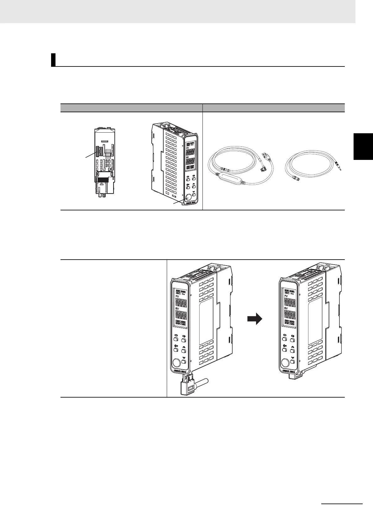
2-4-2 Connection Method
Setup Tool Port and Connecting Cable
The locations of the Setup Tool ports on the E5DC or E5DC-B and the required cables are shown below.
There are Setup Tool ports on both the bottom panel and front panel of the Digital Controller.
* This Cable is required only to connect to the front-panel Setup Tool port.
Connection Procedure
Bottom-panel Port
E5DC/E5DC-B
Setup Tool port Connecting cables
1
Connect the serial connector
to the Setup Tool port on the
bottom panel of the Digital
Controller.
Main Unit Bottom Panel
Main Unit Front Panel
Bottom-panel
Setup
Tool port
Front-panel
Setup Tool port
E58-CIFQ2-E
Conversion Cable*
E58-CIFQ2
USB-Serial Conversion Cable

Table of Contents

Other manuals for Omron E5CC

Questions and Answers:

Question and Answer IconNeed help?

Do you have a question about the Omron E5CC and is the answer not in the manual?

Omron E5CC Specifications

General IconGeneral
Number of Display Digits4 digits
Number of Control Outputs1
Control MethodON/OFF
Input TypeThermocouple, RTD, Analog voltage, Analog current
Supply Voltage100 to 240 VAC
Output TypeRelay, Voltage, Current
Display TypeLCD
Size48 x 48 mm
Mounting MethodPanel mount
Control OutputRelay, Voltage, Current
Alarm OutputRelay
CommunicationRS-485
Ambient Operating Temperature-10 to 55°C
Ambient Operating Humidity25% to 85% RH
Protection RatingIP66

Related product manuals