EasyManuals Logo

Omron E5CC User Manual

Omron E5CC
440 pages
To Next Page IconTo Next Page
To Previous Page IconTo Previous Page
Page #394 background imageLoading...
Page #394 background image
A Appendices
A - 8
E5@C Digital Temperature Controllers User’s Manual (H174)
The Terminal Units of the E5DC-B have male and female connector covers (E53-COV26), respectively.
Order the connector covers separately, if lost or damaged.
The attachment and removal procedure of the connector covers is described below.
Precautions for Correct Use
The product may get damaged.
Take care not to insert the flat-blade screwdriver too much inside the notched part of the female
connector cover.
A-1-7 Connector Cover of the Terminal Unit (models with Push-in Plus
Terminal Blocks)
E53-COV26
Male connector cover Female connector cover
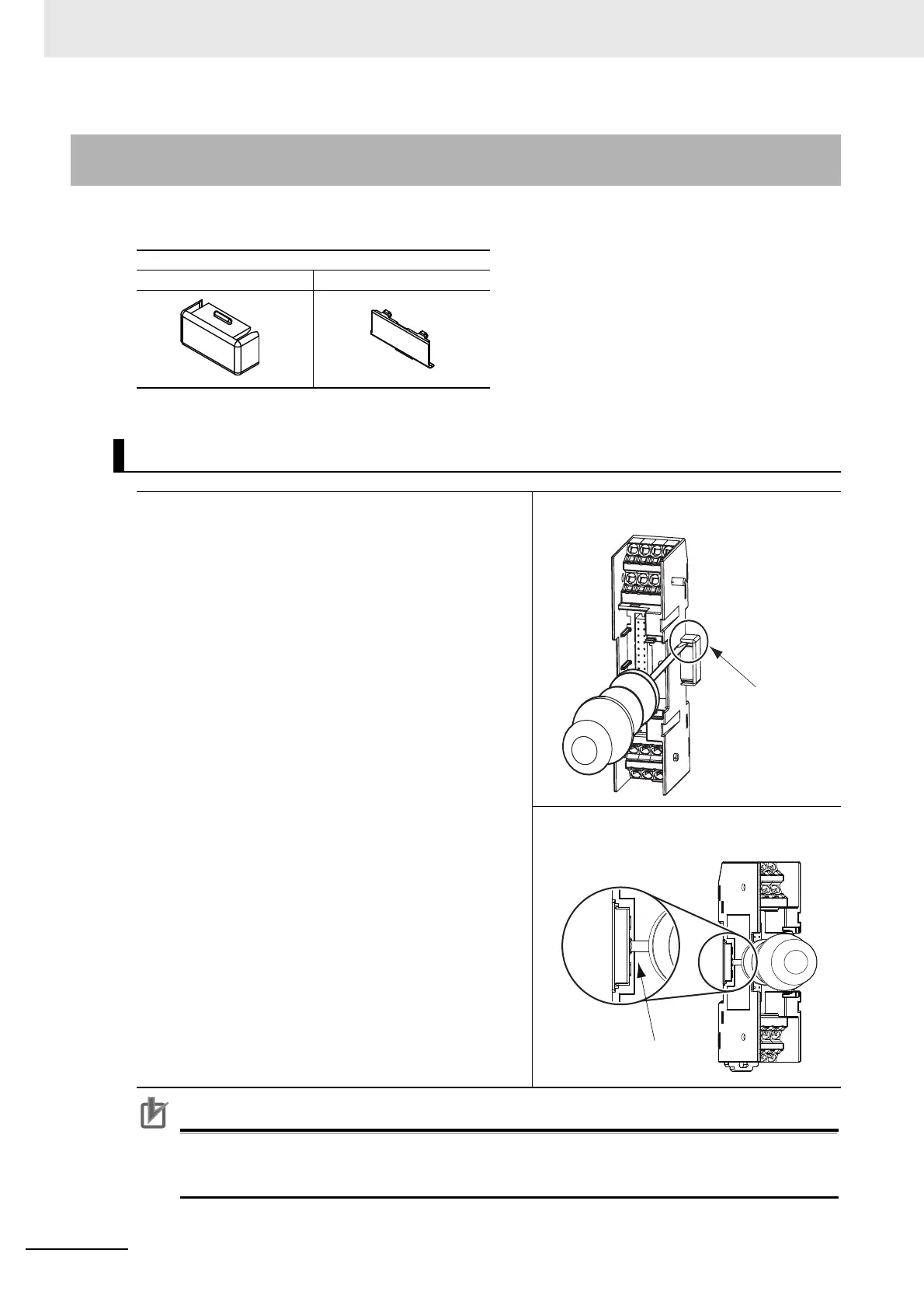
Removing the Connector Covers
1
Insert a flat-blade screwdriver in the notched
part of both the male and female connector
covers, and remove the connector covers.
Notched part
Male connector cover
Notched part
Female connector cover

Table of Contents

Other manuals for Omron E5CC

Questions and Answers:

Question and Answer IconNeed help?

Do you have a question about the Omron E5CC and is the answer not in the manual?

Omron E5CC Specifications

General IconGeneral
Number of Display Digits4 digits
Number of Control Outputs1
Control MethodON/OFF
Input TypeThermocouple, RTD, Analog voltage, Analog current
Supply Voltage100 to 240 VAC
Output TypeRelay, Voltage, Current
Display TypeLCD
Size48 x 48 mm
Mounting MethodPanel mount
Control OutputRelay, Voltage, Current
Alarm OutputRelay
CommunicationRS-485
Ambient Operating Temperature-10 to 55°C
Ambient Operating Humidity25% to 85% RH
Protection RatingIP66

Related product manuals