EasyManuals Logo

Omron E5CC User Manual

Omron E5CC
440 pages
To Next Page IconTo Next Page
To Previous Page IconTo Previous Page
Page #395 background imageLoading...
Page #395 background image
A - 9
A Appendices
E5@C Digital Temperature Controllers User’s Manual (H174)
A-1 Specifications
A
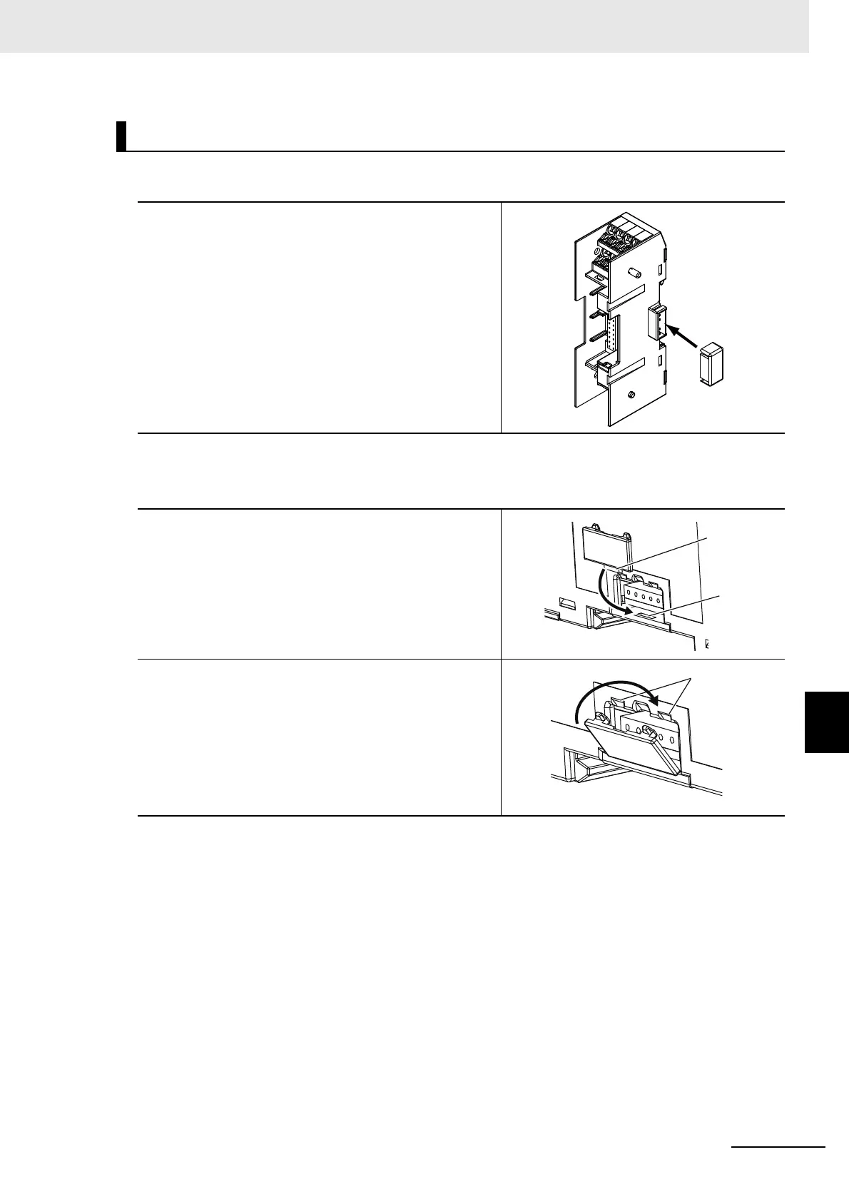
A-1-7 Connector Cover of the Terminal Unit (models
with Push-in Plus Terminal Blocks)
For a male connector cover
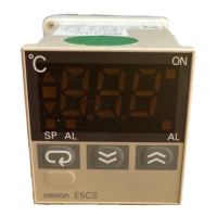
For a female connector cover
Attaching the Connector Covers
1
Attach the connector cover until the claws on
the connector cover fit into the connector with
a click sound.
A male connector does not have an up/down
direction.
1
Insert the projection on the female connector
cover into the groove on the Terminal Unit.
2
Attach the female connector cover until the
claws on the connector cover fit into the
notched part of the Terminal Unit with a click
sound.
Projection
groove
Notched part

Table of Contents

Other manuals for Omron E5CC

Questions and Answers:

Question and Answer IconNeed help?

Do you have a question about the Omron E5CC and is the answer not in the manual?

Omron E5CC Specifications

General IconGeneral
Number of Display Digits4 digits
Number of Control Outputs1
Control MethodON/OFF
Input TypeThermocouple, RTD, Analog voltage, Analog current
Supply Voltage100 to 240 VAC
Output TypeRelay, Voltage, Current
Display TypeLCD
Size48 x 48 mm
Mounting MethodPanel mount
Control OutputRelay, Voltage, Current
Alarm OutputRelay
CommunicationRS-485
Ambient Operating Temperature-10 to 55°C
Ambient Operating Humidity25% to 85% RH
Protection RatingIP66

Related product manuals