EasyManua.ls Logo

Omron E5CS User Manual

Omron E5CS
10 pages
To Next Page IconTo Next Page
Page #1 background imageLoading...
Page #1 background image
R
37
Temperature Controller
E5CS-X
1/16 DIN Sized Controller Offers
Selectable Control, Alarm Modes
H
Accurate to ±0.5% of full scale
H Multiple temperature scale ranges allow
flexibility to match application
H Field-selectable temperature ranges in
°F and °C
H Selectable ON/OFF and PID control
with auto-tuning of proportional band
H 8-function alarm, standard
H Tamper-proof setting, faulty sensor
compensation and controller diagnostics
H Easy-to-read 11 mm high LED display
H Nonvolatile memory backup
H 3-year warranty
RC
Ordering Information
J TEMPERATURE CONTROLLERS
Item Part number
Sensor input type Thermocouple
(Types J and K)
Platinum RTD (Pt: 100 Ω,
DIN and JIS standards)
Interchangeable thermistor
(THE types)
Output
Contact E5CS-R1KJX-F E5CS-R1PX-F E5CS-R1GX-F
Voltage E5CS-Q1KJX-F E5CS-Q1PX-F E5CS-Q1GX-F
Temperature Ranges
Thermocouple Input Type
Input type
Type K Type J
Temperature range 0 to 200 0 to 300 0 to 400 0 to 500 0 to 600 0 to 999 0 to 999 0 to 200 0 to 300 0 to 400 0 t0 500
Scale indication °C °C °C/°F °C/°F °C/°F °C/°F °F °C °C °C/°F °C/°F
Unit of measure 1° C or F
Platinum RTD Input Type
Temperature range
–50 to 50 0.0 to 50.0 –20 to 80 0.0 to 99.9 0 to 200 0 to 300 0 to 400 0 to 600 0 to 800
Scale indication °C °C °C °C/°F °C/°F °C °C/°F °F °F
Unit of measure 1° C or F 0.1° C or F 1° C or F 0.1° C or F 1° C or F
Thermistor Input Type
Temp. range
–50 to 50 0 to 100 50 to 150 100 to 200 150 to 300 –50 to 100 0 to 200 100 to 300 200 to 400 300 to 600
Scale indication °C °F
Unit of measure 1° C or F

Other manuals for Omron E5CS

Question and Answer IconNeed help?

Do you have a question about the Omron E5CS and is the answer not in the manual?

Omron E5CS Specifications

General IconGeneral
Number of Inputs1
Control MethodON/OFF control
Input TypeThermocouple
Supply Voltage100 to 240 VAC 50/60 Hz, or 24 VAC/VDC
Output TypeRelay, Voltage
Setting MethodDigital setting using front panel keys
Dimensions48 x 48 mm
Number of Control Outputs1
Setting Resolution1°C or 0.1°C
Ambient Operating Temperature55 °C
Ambient Operating Humidity85%
Display4-digit LED or LCD

Summary

Temperature Controller Ordering Information

Part Numbers and Specifications

Details part numbers for different sensor input types and output options.

E5CS-X Specifications

Accessories

Optional accessories available for the E5CS-X temperature controller.

Technical Specifications

Details input type, voltage, power, output, response times, and accuracy.

Controller Nomenclature and Dimensions

Key Identification and Displays

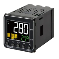
Identifies and describes the function of each key and indicator on the controller.

Physical Dimensions and Mounting

Specifies panel cutout dimensions and side-by-side mounting guidelines.

Controller Connections and Operation

Wiring Diagrams

Illustrates terminal connections for various input and output types.

Initial Setup and Internal Switches

Guides on setting range, alarm modes, and protection switches before power-up.

Function Selector Switch Configuration

Control Mode Selection

Configures ON/OFF or PID control action and proportional period settings.

Control Output Operation and Input Shift

Control Output Modes

Configures controller output for heating (reverse) or cooling (normal) operation.

Input Shift Functionality

Adjusts temperature indication and controls for sensor calibration errors.

Temperature Scale Range Selection

Thermocouple Input Ranges

Defines temperature ranges and scale indications for thermocouple inputs.

RTD and Thermistor Input Ranges

Specifies temperature ranges and scale indications for RTD and thermistor inputs.

Alarm Modes and Setting Protection

Alarm Mode Selection

Covers eight selectable alarm modes, including standby sequence options.

Setting Key Protection

Enables or disables front panel key operations to prevent unauthorized changes.

Troubleshooting Error Codes and Sensor Failures

Error Message Interpretation

Explains error messages like FFF, E11, E33 for troubleshooting sensor or memory failures.

Sensor Failure Indications

Details how sensor failures (break, short-circuit) are indicated and the resulting control output.

Installation, Connections, and Precautions

Mounting and Wiring

Instructions for mounting the controller, attaching adapter, and wiring connections.

Environment and Sequence Precautions

Guidance on installation environment, sensor input wiring, and sequence circuit considerations.

Related product manuals