G-56 Safety Sensors / Components
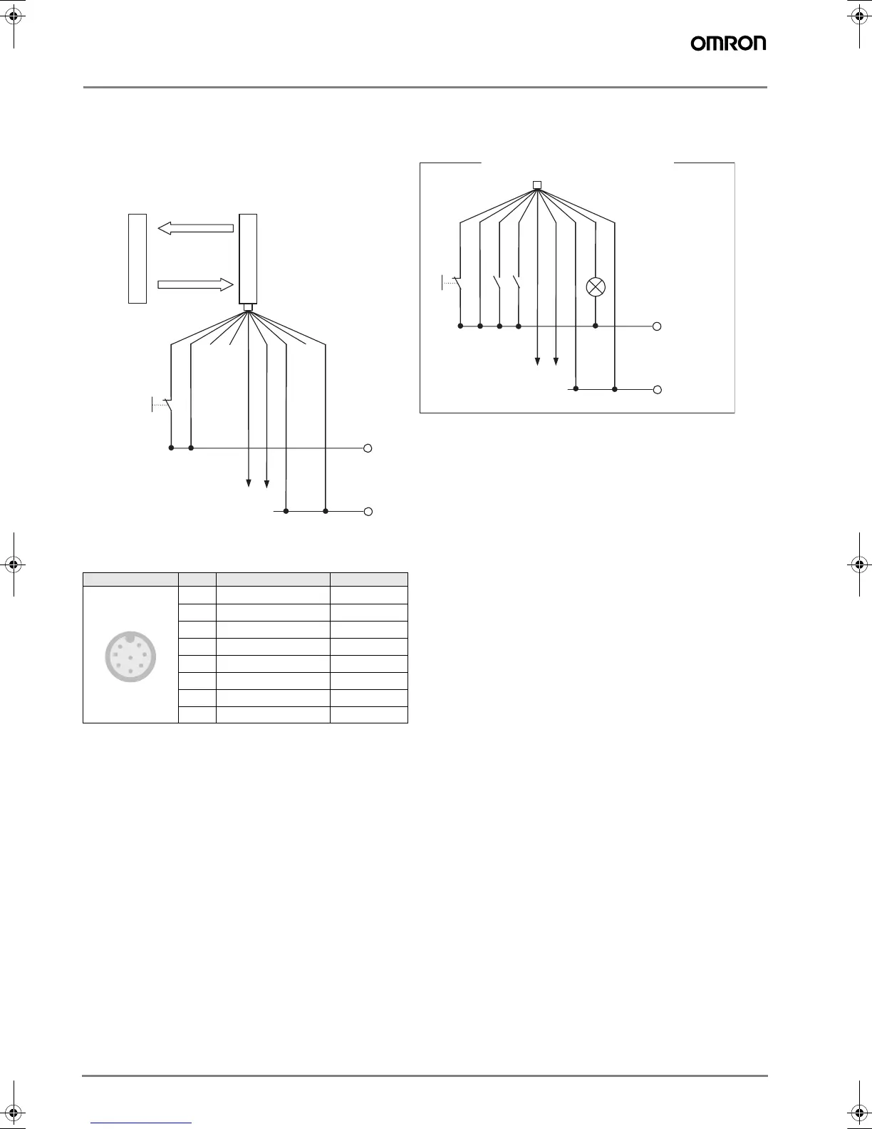
Connection
F3S-TGR-SB@-K@C
Connection example
Pin reference
Front View Pin No. Signal Name Wire Color
1 Test and Reset Input White
2+24Vdc Brown
3 Muting A Input Green
4 Muting B Input Yellow
5 OSSD1 (OUT1) Gray
6 OSSD2 (OUT2) Pink
70Vdc Blue
8 Muting Lamp (0 Vdc) Red
White
Brown
Green
Yellow
Pink
Gray
Blue
Red
Shield
+24Vdc
0Vdc
Active side
Passive side
S1
When using Muting function
S1: External Test / Interlock reset Switch
MIA : Muting input A
MIB : Muting input B
ML : Muting Lamp
OSSD1
OSSD2
White
Brown
Green
Yellow
Pink
Gray
Blue
Red
Shield
+24Vdc
0Vdc
S1
MIA
MIB
ML
OSSD1
OSSD2
In case of Cat 4 (EN954-1), OSSD1/2 must be connected Safety Relay Unit (G9SA, G9SB-301B etc.) with feedback monitor
1
7
2
8
4
5
6
3
F502-EN2-04.book Seite 56 Dienstag, 26. Juli 2005 5:48 17
 Loading...


