F3SJ-E/F3SJ-B/F3SJ-A
38
Install muting sensors so that they can distinguish between the
object that is being allowed to be pass through the detection
zone and a person. If the muting function is activated by the
detection of a person, it may result in serious injury.
Muting lamps (external indicators) that indicate the state of the
muting and override functions must be installed where they are
clearly visible to workers from all the operating positions.
Muting times must be precisely set according to the application
by qualified personnel who have received appropriate training.
In particular, if the muting time limit is to be set to infinity, the
person who makes the setting must bear responsibility.
Use two independent input devices for the muting inputs.
Install the F3SJ, Muting Sensors, or a protective wall so that
workers cannot enter hazardous areas while muting is in effect,
and set muting times.
Position the switch that is used to activate the override function
in a location where the entire hazardous area can be seen, and
where the switch cannot be operated from inside the hazardous
area. Make sure that nobody is in the hazardous area before
activating the override function.
Install the sensor system so that it is not affected by reflective
surfaces. Failure to do so may hinder detection, resulting in
serious injury.
When using more than 1 set of F3SJ, install them so that mutual
interference does not occur, such as by configuring series
connections or using physical barriers between adjacent sets.
Make sure that the F3SJ is securely mounted and its cables and
connectors are properly secured.
Make sure that no foreign material, such as water, oil or dust,
enters the inside of the F3SJ while the cap is removed.
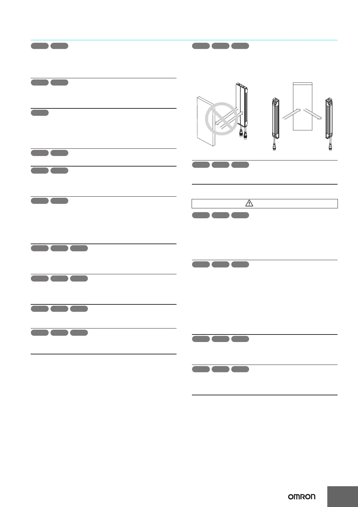
Do not use the sensor system with mirrors in a regressive
reflective configuration. Doing so may hinder detection. It is
possible to use mirrors to "bend" the detection zone to a 90-
degree angle.
When using series connections, perform inspection of all
connected F3SJs as instructed in the User's Manual.
For wiring
[For PNP output]
Connect the load between the output and 0V line.
[For NPN output]
Connect the load between the output and +24V line. If +24 V and
0 V are connected, it is dangerous because operation mode is
inversed to "ON when interrupted".
[For PNP output]
Do not short-circuit an output line to +24 V line. Otherwise, the
output is always ON. Also, 0 V of the power supply must be
grounded so that output should not turn ON due to grounding of
the output line.
[For NPN output]
Do not short-circuit an output line to 0 V line. Otherwise, the
output is always ON. Also, +24 V of the power supply must be
grounded so that output should not turn ON due to grounding of
the output line.
Configure the system by using the optimal number of safety
outputs that satisfy the requirements of the necessary safety
category.
Do not connect each line of F3SJ to a DC power supply higher
than 24 V+20%. Also, do not connect to an AC power supply.
Failure to do so may result in electric shock.
WARNING
Reflector
Position with retro-reflection
Position with detection
zone bent at 90°
Reflector
F3SJ-B F3SJ-A
F3SJ-B F3SJ-A
F3SJ-B F3SJ-A

 Loading...


