9
•
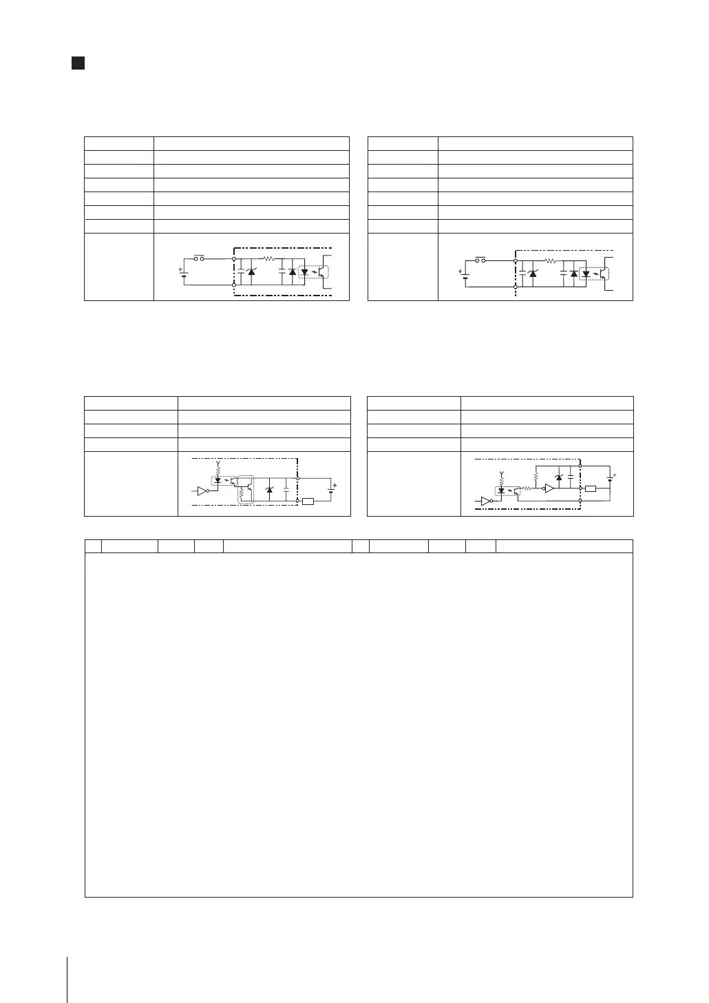
I/O Connector
No. Wire color
Mark (red)
Function
Signal name
No. Wire color
Mark (blk)
Function
Signal name
Output terminal
COM IN
Input voltage
ON current *1
ON voltage *1
OFF current *2
OFF voltage *2
ON delay
OFF delay
Internal circuit
12 to 24 V DC ±10 %
5 mA min.
8.8 V min.
0.5 mA max.
1.1V max.
5 ms max.
0.7 ms max.
[Input] signals:
STEP0/ENCTRIG_Z0, STEP1/ENCTRIG_Z1,
ENCTRIG_A0 to 1, ENCTRIG_B0 to 1
*1 ON current/ON voltage
This refers to the current or voltage values needed to shift from the OFF → ON state. The ON voltage value is the potential
difference between each of the input terminals and COM IN.
*2 OFF current/OFF voltage
This refers to the current or voltage values needed to shift from the ON → OFF state. The OFF voltage value is the potential
difference between each of the input terminals and COM IN.
[Output] signals:
Output voltage
Load current
ON residual voltage
OFF leakage current
Internal circuit
12 to 24 V DC ±10 %
45 mA max.
2 V max.
0.2 mA max.
Input voltage
ON current *1
ON voltage *1
OFF current *2
OFF voltage *2
ON delay
OFF delay
Internal circuit
12 to 24 V DC ±10 %
5 mA min.
8.8 V min.
0.5 mA max.
0.8 V max.
0.1 ms max.
0.1 ms max.
Output voltage
Load current
ON residual voltage
OFF leakage current
Internal circuit
12 to 24 V DC ±10 %
45 mA max.
2 V max.
0.2 mA max.
•
Internal Specifications
[Input] signals: RESET, DI0 to DI7, DSA0, DSA1
PNP I/O type
FZ3-305-10/FZ3-355-10/FZ3-H305-10/FZ3-H355-10/FZ3-705-10/FZ3-755-10/FZ3-H705-10
FZ3-H755-10/FZ3-905-10/FZ3-955-10/FZ3-H905-10/FZ3-H955-10/FZD-505-10/FZD-555-10
Parallel Interface
BUSY0, RUN/BUSY1, OR0 to 1, GATE0 to 1,
ERROR, DO0 to 15, READY0 to 1
[Output] signals: When STGOUT0-3 are not used,
connect the COM IN terminal.
COM IN
Input terminal
COM OUT
Output terminal
Load
COM IN
Input terminal
㩷
COM OUT
Load
I/O Connector wiring is the same as NPN I/O type.
fz3_4ch_setup_E.book Page 9 Friday, August 7, 2009 5:45 PM

 Loading...


