10
LCD integrated type
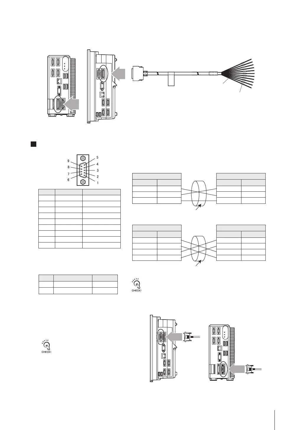
Pin numbers will depend on the external device being connected. Refer
to the manual for the personal computer or PLC being connected.
Turn OFF the power supply before connecting or
disconnectin g a Parallel I/O Cable. Peripheral
devices may be damaged if the cable is connected
or disconnected with the power ON.
Pin No.
1
2
3
4
5
6
7
8
9
Signal name
SDB(+)
SD/SDA(-)
RD/RDA(-)
RDB(+)
NC
NC
NC
NC
GND
Function
For RS-422
For RS-232C/RS-422
For RS-232C/RS-422
For RS-422
Not connected
Not connected
Not connected
Not connected
Signal ground
•
Connector
•
Connection Method
•
Wiring
• RS-232C
• RS-422
Controller
Use a shielded cable.
The maximum cable length is 15 m.
Use a compatible connector.
• Recommended items
RS/CS control cannot be used.
Align the connector with the socket and
press it straight into place, then fix it with
the screws on both sides of the connector.
XM2A-0901
XM2S-0911
OMRON Corporation
OMRON Corporation
Box type
Signal name
SD
RD
GND
Pin No.
2
3
9
Signal name
SD
RD
GND
Pin No.
*
*
*
External device to be connected
Controller
Use a shielded cable.
Signal name
SDB(+)
SDA(-)
RDA(-)
RDB(+)
Pin No.
1
2
3
4
Pin No.
*
*
*
*
External device to be connected
Signal name
SDA(-)
SDB(+)
RDB(+)
RDA(-)
FZ-VP (2 m, 5 m)
Wire Color
No. mark
LCD integrated type
Box type
Plug
Hood
Manufacturer Model
•
Connector
Connect the optional parallel I/O cable (FZ-VP).
Serial Interface
fz3_4ch_setup_E.book Page 10 Friday, August 7, 2009 5:45 PM

 Loading...


