11
•
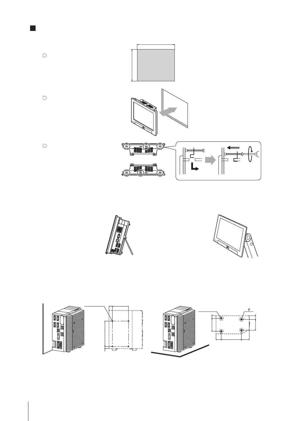
LCD integrated type
Make a mount hole on the panel.
Panel thickness range: 1.6 to 4.8 mm
Panel material: Metal (iron, aluminum
or stainless)
Insert the LCD integrated controller
into the hole, from the front panel.
• Panel mounting
•
Box type
• Side mounting • Bottom mounting
* No burr allowed
Use the bracket (supplied with the
product) to secure the controller
and the panel.
Tightening torque: 0.5 to 0.6 Nm
297
+
1
0
247
(Unit: mm)
126 ± 0.25
80 ± 0.25
4-M4 Depth 6
100
± 0.25
64
±
0.25
(26)
(17)
20
(13)
(11)
(18)
54
±
0.25
()
39
4-M4 Depth 6
Top face
Bottom face
+
1
0
Mounting
1
2
3
• Mounting the controller to the optional
desktop stand.
The controller can be placed on
a desk by attaching the optional
desktop stand (FZ-DS) to the
rear of the controller.
* For details, refer to the instruction
manual of the desktop stand.
• Mounting the controller to the optional
VESA attachment unit.
VESA-compatible mounting of
the controller is possible by
attaching the optional VESA
attachment unit (FZ-VESA) to
the rear of the controller.
* For details, refer to the instruction
manual of the VESA attachment
4-
* When mounting the controller on its bottom, it must be fixed
without removing the feet to reserve ventilation path.
fz3_4ch_setup_E.book Page 11 Friday, August 7, 2009 5:45 PM

 Loading...


