EasyManua.ls Logo

Omron G3NA User Manual

Omron G3NA
16 pages
To Next Page IconTo Next Page
Page #1 background imageLoading...
Page #1 background image
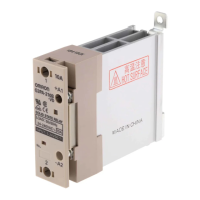
Solid State Relays G3NA 1
Solid State Relays
G3NA
The reliable choice for Hockey-puck-style
Solid State Relays. Available in a Wide
Range of Currents.
All models feature the same compact dimensions to provide a
uniform mounting pitch.
Built-in varistor effectively absorbs external surges.
Operation indicator enables monitoring operation.
Protective cover for greater safety.
Certified by UL, CSA, and TÜV.
Model Number Structure
Model Number Legend
1. Basic Model Name
G3NA: Solid State Relay
2. Load Power Supply
Blank: AC output
D: DC output
3. Rated Load Power Supply Voltage
2: 200 VAC or 200 VDC
4: 400 VAC
4. Rated Load Current
Note: Not all combinations of current and voltage are available.
05: 5 A
10: 10 A
20: 20 A
25: 25 A
40: 40 A
50: 50 A
75: 75 A
90: 90 A
5. Terminal Type
B: Screw terminals
6. Zero Cross Function
Blank: Equipped with zero cross function
(AC-output models only)
7. Certification
Blank: Models certified by UL and CSA
UTU: Certified by UL, CSA, and TÜV
1
2
3 4 5 6 7
G3NA-@@@@@-@
Question and Answer IconNeed help?

Do you have a question about the Omron G3NA and is the answer not in the manual?

Omron G3NA Specifications

General IconGeneral
CategorySolid State Relay
Mounting TypePanel Mount
Control Voltage5-24V DC
Output TypeAC
Dielectric Strength2500V AC
Load Voltage24 – 240 VAC

Summary

Model Number Structure

Model Number Legend

Explains the coding system for model numbers.

Ordering Information

List of Models

Lists available Solid State Relay models with key specifications.

Accessories

Mounting Accessories

Details one-touch mounting plates, brackets, and heat sinks.

Specifications

Ratings

Electrical ratings for input and output of the relays.

Characteristics

Engineering Data

Load Current vs. Ambient Temperature

Graphs showing load current derating based on ambient temperature.

One Cycle Surge Current

Thermal Resistance

Thermal Resistance Rth (Back of Junction SSR)

Thermal resistance values for the SSR's junction.

Thermal Resistance Rth of Heat Sinks

Thermal resistance values for various heat sinks.

Dimensions

Relay Dimensions

Physical dimensions and mounting hole information for G3NA relays.

Options

Mounting Plates and Brackets

Accessories for mounting relays on DIN tracks or panels.

Heat Sinks

Various heat sinks for improving thermal performance.

Safety Precautions

Electrical and Thermal Hazards

Warnings about electric shock, burns, and fire due to heat.

Safe Use and Heat Management

Proper operation, heat dissipation, and preventing overheating.

Installation and Handling

Correct screw tightening, handling procedures, and fan safety.

Operating Conditions and Limitations

Adhering to rated values, frequency ranges, and environmental conditions.

Operating and Storage Locations

Precautions for Correct Use

Before Actual Operation

Essential checks and considerations before initial operation.

Mounting Method

SSR Installation Guidelines

Covers SSR spacing, duct height, and ventilation for efficient heat dissipation.

Noise Terminal Voltage Compliance

Reverse Connection Protection

Loss Time Considerations

DC Load Usage

Fuses for Short-Circuit Protection

Operating and Storage Environment Precautions

Ambient Temperature and Transportation

Management of ambient temperature and safe transportation practices.

Operation Precautions

Leakage Current and Wiring Safety

Safety measures for leakage current and proper wiring.

Screw Tightening and Handling

Importance of correct screw torque and careful handling to prevent damage.

Warranty and Application Considerations

Warranty and Liability

OMRON's warranty terms and limitations of liability.

Product Suitability and Disclaimers

Customer responsibility for product suitability and performance data disclaimers.

Related product manuals