Precautions for All Relays
Refer to the Safety Precautions section for each Relay for specific precautions applicable to that Relay.
■ Precautions for Safe Use
These precautions are required to ensure safe operation.
• Do not touch the charged Relay terminal area or the charged
socket terminal area while the power is turned ON. Doing so may
result in electric shock.
• Do not use a Relay for a load that exceeds the Relay's switching
capacity or other contact ratings. Doing so will reduce the specified
performance, causing insulation failure, contact welding, and
contact failure, and the Relay itself may be damaged or burnt.
• Do not drop or disassemble Relays. Doing so may reduce Relay
characteristics and may result in damage, electric shock, or
burning.
• Relay durability depends greatly on the switching conditions.
Confirm operation under the actual conditions in which the Relay
will be used. Make sure the number of switching operations is
within the permissible range. If a Relay is used after performance
has deteriorated, it may result in insulation failure between circuits
and burning of the Relay itself.
• Do not apply overvoltages or incorrect voltages to coils, or
incorrectly wire the terminals. Doing so may prevent the Relay from
functioning properly, may affect external circuits connected to the
Relay, and may cause the Relay itself to be damaged or burnt.
• Do not use Relays where flammable gases or explosive gases may
be present. Doing so may cause combustion or explosion due to
Relay heating or arcing during switching.
• Perform wiring and soldering operations correctly and according to
the instructions contained in Precautions for Correct Use given
below. If a Relay is used with faulty wiring or soldering, it may
cause burning due to abnormal heating when the power is turned
ON.
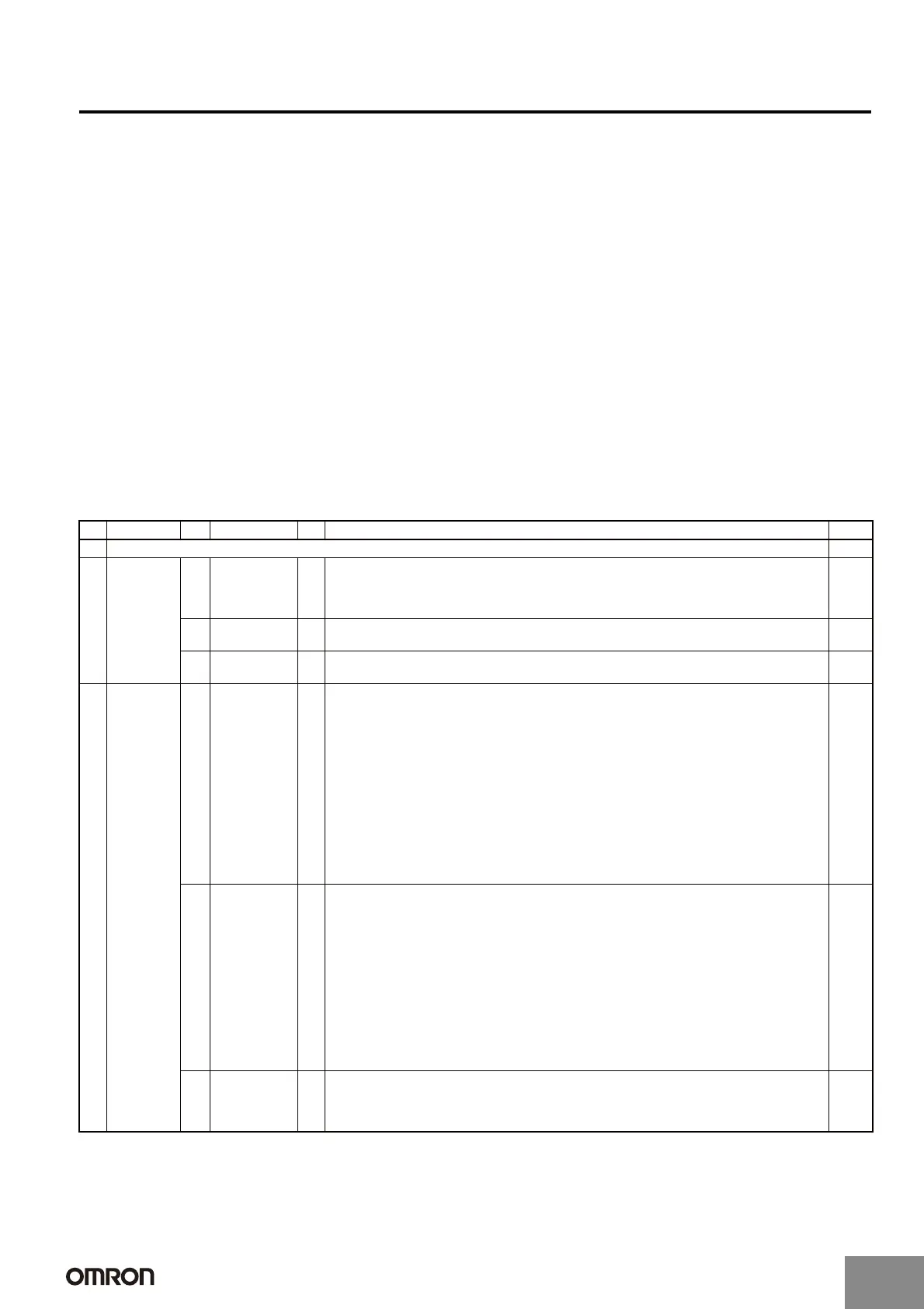
■ Precautions for Correct Use
Contents
No. Area No. Classification No. Item Page
A Using Relays
C-3
B Selecting
Rela
ys
A Mounting
S
tructure and
Type of
Protection
1
2
3
Type of Protection
Combining Relays and Sockets
Using Relays in Atmospheres Subject to Dust
C-4
B Drive Circuits 1
2
Providing Power Continuously for Long Periods
Operation Checks for Inspection and Maintenance
C-4
C Loads 1
2
Contact Ratings
Using Relays with a Microload
C-4
C Circuit
Design
A Load Circuits 1
2
3
4
5
6
7
8
9
10
11
Load Switching
A Resistive Loads and Inductive Loads
B Switching Voltage
C Switching Current
Electrical Durability
Failure Rates
Contact Protection Circuits
Countermeasures for Surge from External Circuits
Connecting Loads for Multi-pole Relays
Motor Forward/Reverse Switching
Power Supply Double Break with Multi-pole Relays
Short-circuiting Due to Arcing between NO and NC Contacts in SPDT Relays
Using SPST-NO/SPST-NC Contact Relays as an SPDT Relay
Connecting Loads of Differing Capacities
C-5
B Input Circuits 1
2
3
4
5
6
7
8
9
10
11
12
13
Maximum Allowable Voltage
Voltage Applied to Coils
Changes in Must-operate Voltage Due to Coil Temperature
Applied Voltage Waveform for Input Voltage
Preventing Surges when the Coil Is Turned OFF
Leakage Current to Relay Coils
Using with Infrequent Switching
Configuring Sequence Circuits
Connecting Relay Grounds
Individual Specifications for Must-operate/release Voltages and Operate/Release Times
Using DC-operated Relays, (1) Input Power Supply Ripple
Using DC-operated Relays, (2) Coil Polarity
Using DC-operated Relays, (3) Coil Voltage Insufficiency
C-7
C Mounting
Design
1
2
3
4
Lead Wire Diameters
When Sockets are Used
Mounting Direction
When Devices Such as Microcomputers are in Proximity
C-9
http://www.ia.omron.com/
C-2
(c)Copyright OMRON Corporation 2007 All Rights Reserved.
Artisan Technology Group - Quality Instrumentation ... Guaranteed | (888) 88-SOURCE | www.artisantg.com

 Loading...


