C-A-4 Contact Protection Circuits
Using a contact protection circuit is effective in increasing contact
durability and minimizing the production of carbides and nitric acid.
The following table shows typical examples of contact protection
circuits. Use them as guidelines for circuit design.
1. Depending on factors such as the nature of the load and the
Relay characteristics, the effects may not occur at all or adverse
effects may result. Therefore be sure to check operation under
the actual load conditions.
2. When a contact protection circuit is used, it may cause the
release time (breaking time) to be increased. Therefore be sure to
check operation under the actual load conditions.
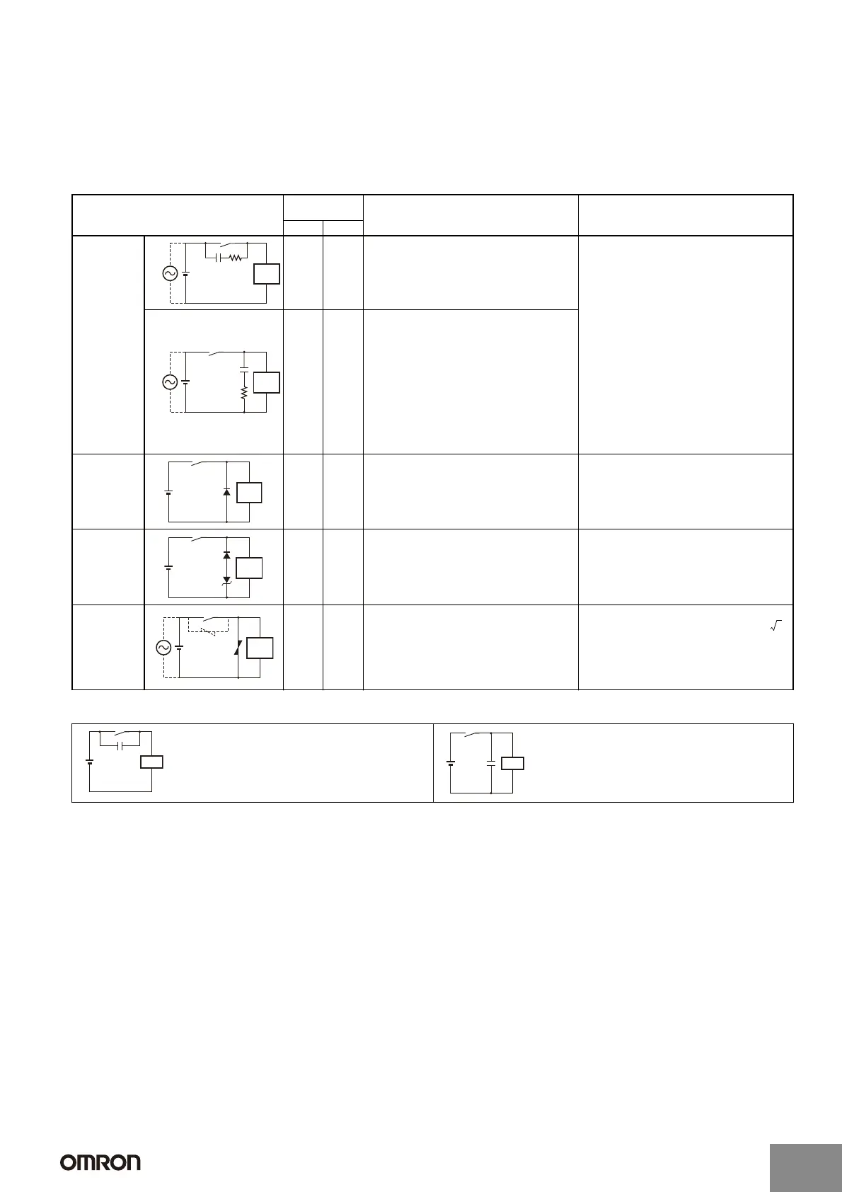
Typical Examples of Contact Protection Circuits
Do not use the following types of contact protection circuit.
Note: Although it is thought that switching a DC inductive load is more difficult than a resistive load, an appropriate contact protection circuit can achieve almost the
same characteristics.
C-A-5 Countermeasures for Surge from External
Circuits
Install contact protection circuits, such as surge absorbers, at
locations where there is a possibility of surges exceeding the Relay
withstand voltage due to factors such as lightning. If a voltage
exceeding the Relay withstand voltage value is applied, it will cause
line and insulation deterioration between coils and contacts and
between contacts of the same polarity.
Circuit example Applicable
current
Features and remarks Element selection
AC DC
CR
*See
remarks.
(Yes)
Yes *Load impedance must be much smaller than
the CR circuit impedance when using the Relay
for an AC voltage.
When the contacts are open, current flows to the
inductive load via CR.
Use the following as guides for C and R values:
C: 0.5 to 1 μF per 1 A of contact current (A)
R: 0.5 to 1
Ω per 1 V of contact voltage (V)
These values depend on various factors,
including the load characteristics and variations
in characteristics. Confirm optimum values
experimentally.
Capacitor C suppresses the discharge when the
contacts are opened, while the resistor R limits
the current applied when the contacts are closed
the next time.
Generally, use a capacitor with a dielectric
strength of 200 to 300 V. For applications in an
AC circuit, use an AC capacitor (with no polarity).
If there is any question about the ability to cut off
arcing of the contacts in applications with high
DC voltages, it may be more effective to connect
the capacitor and resistor across the contacts,
rather than across the load. Perform testing with
the actual equipment to determine this.
Yes Yes The release time of the contacts will be
increased if the load is a Relay or solenoid.
Diode No Yes The electromagnetic energy stored in the
inductive load reaches the inductive load as
current via the diode connected in parallel, and
is dissipated as Joule heat by the resistance of
the inductive load. This type of circuit increases
the release time more than the CR type.
Use a diode having a reverse breakdown voltage
of more than 10 times the circuit voltage, and a
forward current rating greater than the load
current. A diode having a reverse breakdown
voltage two or three times that of the supply
voltage can be used in an electronic circuit
where the circuit voltage is not particularly high.
Diode + Zener
diode
No Yes This circuit effectively shortens the release time
in applications where the release time of a diode
circuit is too slow.
The breakdown voltage of the Zener diode
should be about the same as the supply voltage.
Varistor Yes Yes This circuit prevents a high voltage from being
applied across the contacts by using the
constant-voltage characteristic of a varistor. This
circuit also somewhat increases the release
time. Connecting the varistor across the load is
effective when the supply voltage is 24 to 48 V,
and across the contacts when the supply voltage
is 100 to 240 V.
The cutoff voltage Vc must satisfy the following
conditions. For AC, it must be multiplied by .
Vc > (Supply voltage
× 1.5)
If Vc is set too high, its effectiveness will be
reduced because it will fail to cut off high
voltages.
This circuit arrangement is very effective for diminishing
arcing at the contacts when breaking the circuit. However,
since electrical energy is stored in C (capacitor) when the
contacts are open, the current from C flows into the
contacts when they close. This may lead to contact
welding.
This circuit arrangement is very useful for diminishing
arcing at the contacts when breaking the circuit. However,
since the charging current to C flows into the contacts
when they are closed, contact welding may occur.
Power
supply
(See
remarks.)
CR
Inductive
load
(See
remarks.)
C
R
Power
supply
Inductive
load
Power
supply
Inductive
load
Inductive
load
Power
supply
Inductive
load
Power
supply
2
LoadPower
supply
C
LoadPower
supply
C
http://www.ia.omron.com/
C-6
(c)Copyright OMRON Corporation 2007 All Rights Reserved.
Artisan Technology Group - Quality Instrumentation ... Guaranteed | (888) 88-SOURCE | www.artisantg.com

 Loading...


