G-10 Automatic Mounting of PCB Relays
A Through-hole PCBs
When mounting a Relay to a PCB, take the following points into consideration for each
process. There are also certain mounting precautions for individual Relays, so refer to the
individual Relay precautions as well.
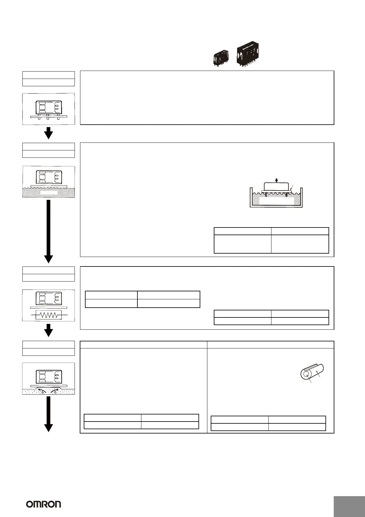
Process 1
Placement
1. Do not bend any terminals of the Relay to use it as a self-clinching Relay.
The initial performance characteristics of the Relay will be lost.
2. Execute PCB processing correctly according to the PCB process diagrams.
Process 2
Flux Application
Flux
1. The G7S has no protection against flux
penetration, so absolutely do not use the method
shown in the diagram on the right, in which a
sponge is soaked with flux and the PCB pressed
down on the sponge. If this method is used for the
G7S, it will cause the flux to penetrate into the
Relay. Be careful even with the flux-resistant
G7SA, because flux can penetrate into the Relay
if it is pressed too deeply into the sponge.
2. The flux must be a non-corrosive rosin-based flux
suitable for the Relay's structural materials.
For the flux solvent, use an alcohol-based solvent,
which tends to be less chemically reactive.
Apply the flux sparingly and evenly to prevent
penetration into the Relay.
When dipping the Relay terminals into liquid flux,
be sure to adjust the flux level, so that the upper
surface of the PCB is not flooded with flux.
3. Make sure that flux does not adhere anywhere
outside of the Relay terminals. If flux adheres to
an area such as the bottom surface of the Relay, it
will cause the insulation to deteriorate.
Applicability of Dipping Method
G7S G7SA
NO YES
(Must be checked when
spray flexor is used.)
Pressing deeply
Relay
Sponge soaked with
flux
PCB
Example of incorrect method
Process 3
Preheating
Heater
1. Preheating is required to create the optimum
conditions for soldering.
2. The following conditions apply for preheating.
3. Do not use a Relay if it has been left at a high
temperature for a long period of time due to a
circumstance such as equipment failure. These
conditions will cause the Relay's initial
characteristics to change.
Applicability of Preheating
Temperature 100°C max.
Time 1 min max.
G7S G7SA
NO YES
Note: For lead-free solder, perform the soldering under conditions that conform to the applicable specifications.
Automatic soldering Manual soldering
1. Flow soldering is recommended to assure a uniform
solder joint.
• Solder: JIS Z3282 or H63A
• Solder temperature and soldering time: Approx. 250°C
(DWS: Approx. 260°C)
• Solder time: 5 s max. (DWS: Approx. 2 s for first time
and approx. 3 s for second time)
• Adjust the level of the molten solder so that the PCB is
not flooded with solder.
Applicability of Automatic Soldering
1. Smooth the solder with the tip of the iron, and then
perform the soldering under the following conditions.
• Solder: JIS Z3282, H60A, or H63A
(containing rosin-based flux)
• Soldering iron: Rated at 30 to 60 W
• Tip temperature: 280 to 300°C
• Soldering time: Approx. 3 s max.
2. As shown in the above illustration, solder is available
with a cut section to prevent flux from splattering.
Applicability of Manual Soldering
G7S G7SA
NO YES
Solder
Flux
G7S G7SA
YES YES
Process 4
Soldering
Continued next
page.
http://www.ia.omron.com/
C-13
(c)Copyright OMRON Corporation 2007 All Rights Reserved.
Artisan Technology Group - Quality Instrumentation ... Guaranteed | (888) 88-SOURCE | www.artisantg.com

 Loading...


