F Handling Relays
F-1 Vibration and Shock
Relays are precision components. Regardless of whether or not they
are mounted, do not exceed the rated values for vibration and shock.
The vibration and shock values are determined individually for each
Relay, so check the individual Relay specifications in this catalog.
If a Relay is subjected to abnormal vibration or shock, its original
performance capabilities will be lost.
F-2 Dropped Products
Do not use a product that has been dropped, or that has been taken
apart. Not only may its characteristics not be satisfied, but it may be
susceptible to damage or burning.
G Relays for Printed Circuit Boards
(PCBs)
G-1 Selecting PCBs
(1) PCB Materials
PCBs are classified into those made of epoxy and those made of
phenol. The following table lists the characteristics of these PCBs.
Select one, taking into account the application and cost. Epoxy PCBs
are recommended for mounting Relays to prevent the solder from
cracking.
G-2 Selecting PCBs
(2) PCB Thickness
The PCB may warp due to the size, mounting method, or ambient
operating temperature of the PCB or the weight of components
mounted to the PCB. Should warping occur, the internal mechanism
of the Relay on the PCB will be deformed and the Relay may not
provide its full capability. Determine the thickness of the PCB by
taking the material of the PCB into consideration.
In general, PCB thickness should be 0.8, 1.2, 1.6, or 2.0 mm. Taking
Relay terminal length into consideration, the optimum thickness is
1.6 mm.
G-3 Selecting PCBs
(3) Terminal Hole and Land Diameters
Refer to the following table to select the terminal hole and land
diameters based on the Relay mounting dimensions. The land
diameter may be smaller if the land is processed with through-hole
plating.
G-4 Mounting Space
A Ambient Temperature
When mounting a Relay, check this catalog for the specified amount
of mounting space for that Relay, and be sure to allow at least that
much space.
When two or more Relays are mounted, their interaction may
generate excessive heat. In addition, if multiple PCBs with Relays
are mounted to a rack, the temperature may rise excessively. When
mounting Relays, leave enough space so that heat will not build up,
and so that the Relays' ambient temperature remains within the
specified operating temperature range.
B Mutual Magnetic Interference
When two or more Relays are mounted, Relay characteristics may
be changed by interference from the magnetic fields generated by
the individual Relays. Be sure to conduct tests using the actual
devices.
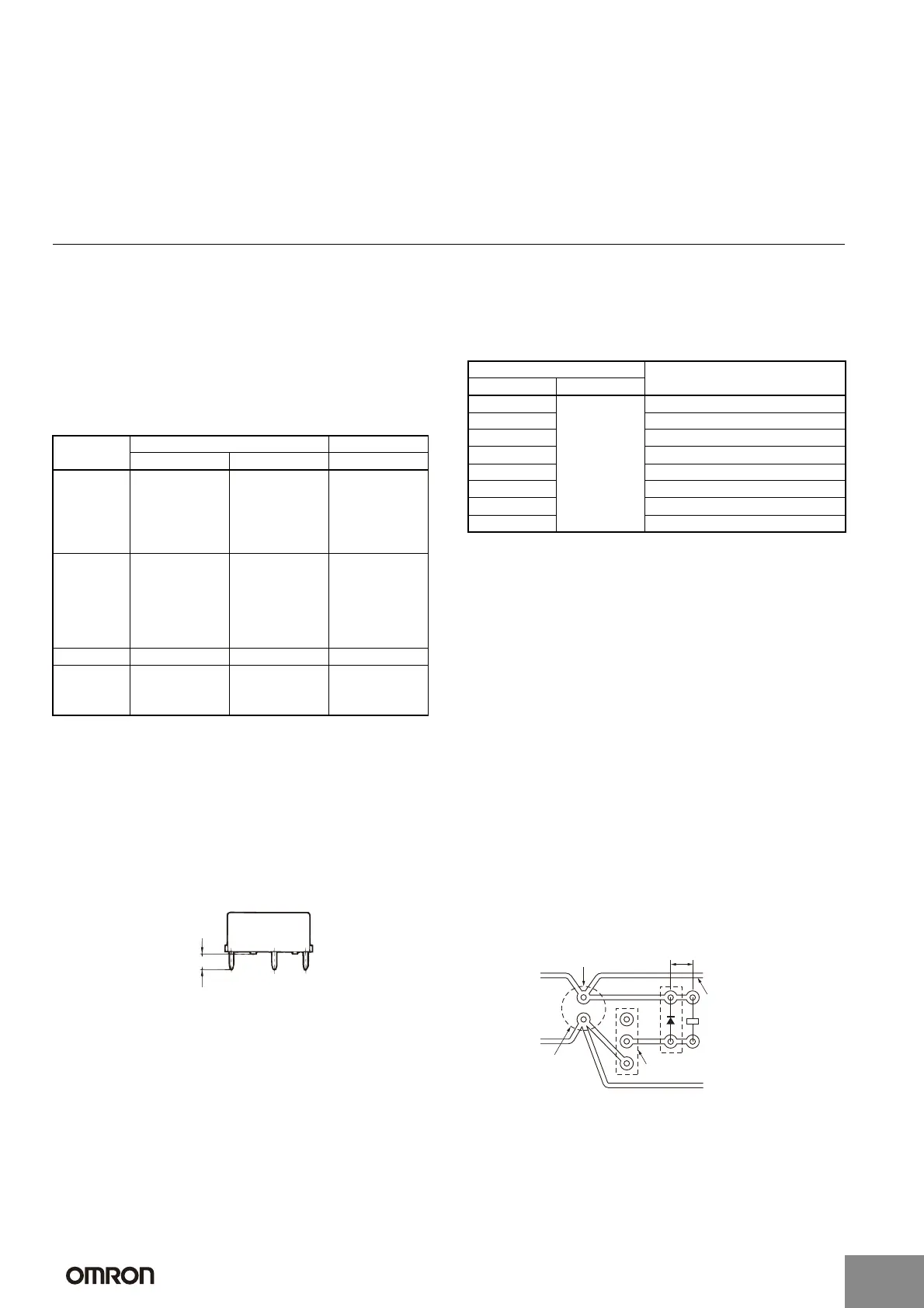
G-5 Pattern Design for Noise Countermeasures
A Noise from Coils
When the coil is turned OFF, reverse power is generated to both
ends of the coil and a noise spike occurs. As a countermeasure,
connect a surge absorbing diode. The diagram below shows an
example of a circuit for reducing noise propagation.
Material Epoxy Phenol
Item Glass epoxy (GE) Paper epoxy (PE) Paper phenol (PP)
Electrical
characteristics
• High insulation
resistance.
• Insulation
resistance hardly
affected by
moisture
absorption.
Characteristics
between glass
epoxy and phenol
New PCBs are
highly insulation-
resistive but easily
affected by
moisture
absorption.
Mechanical
characteristics
• The dimensions
are not easily
affected by
temperature or
humidity.
• Suitable for
through-hole or
multi-layer PCBs.
Characteristics
between glass
epoxy and phenol
• The dimensions
are easily
affected by
temperature or
humidity.
• Not suitable for
through-hole
PCBs.
Relative cost High Moderate Low
Applications Applications that
require high
reliability.
Characteristics
between glass
epoxy and phenol
Applications in
comparatively good
environments with
low-density wiring.
Terminal length
Terminal hole diameter (mm) Minimum land diameter (mm)
Nominal value Tolerance
0.6 ±0.1 1.5
0.8 1.8
1.0 2.0
1.2 2.5
1.3 2.5
1.5 3.0
1.6 3.0
2.0 3.0
Smoothing
capacitor
Relay drive transistor
Power supply lin
Noise is superimposed
on the power supply line,
so a separate pattern is
connected from a
smoothing capacitor to
supply coil power.
The pattern will
form an antenna
circuit, so make
it as short as
possible.
http://www.ia.omron.com/
C-11
(c)Copyright OMRON Corporation 2007 All Rights Reserved.
Artisan Technology Group - Quality Instrumentation ... Guaranteed | (888) 88-SOURCE | www.artisantg.com

 Loading...


