3-6
z Siemens PLC Memory Allocations
Start address End address Contents Description
V0 V19 RS-232C send command Data sent by the Standard PLC to the
G9SP-series Controller
V100 D299 RS-232C reception response Data received by the Standard PLC from
the G9SP-series Controller
M0 M7 Checksum calculation work area Work area for RS-232C communications.
Used to calculate the check-sum
I0 I3 G9SP communications reception data
(written to G9SP-series Controller)
Data written to G9SP-series Controller from
Standard PLC. Stored in the communica-
tions reception data of the G9SP-series
Controller.
Q0 Q3 G9SP communications transmission
data (read from the G9SP-series Con-
troller)
Communications data sent from the G9SP-
series Controller is read.
Q4 Q9 G9SP Safety Input terminal data (read
from the G9SP-series Controller)
Safety Input terminal data of the G9SP-
series Controller is read.
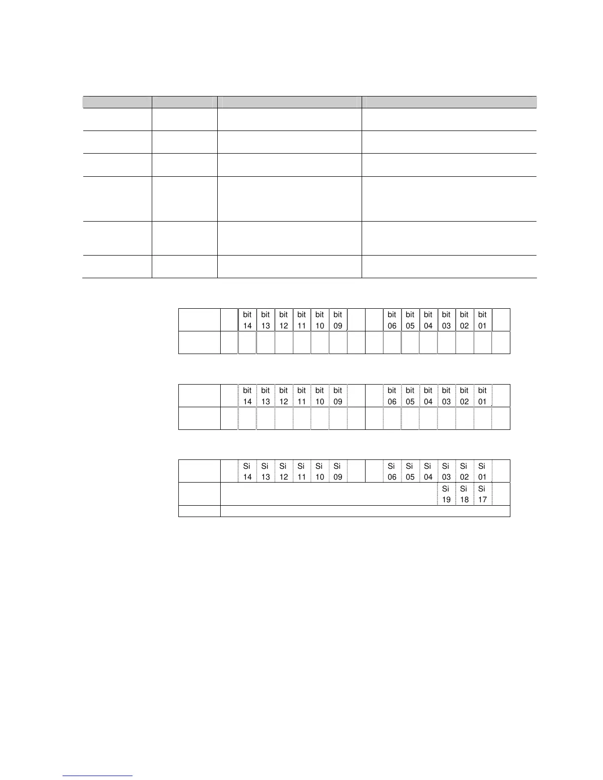
- G9SP Communications Reception Data
15 8 7 0
I0-I1 bit
15
bit
14
bit
13
bit
12
bit
11
bit
10
bit
09
bit
08
bit
07
bit
06
bit
05
bit
04
bit
03
bit
02
bit
01
bit
00
I2-I3 bit
31
bit
30
bit
29
bit
28
bit
27
bit
26
bit
25
bit
24
bit
23
bit
22
bit
21
bit
20
bit
19
bit
18
bit
17
bit
16
- G9SP Communications Transmission Data
15 8 7 0
Q0-Q1 bit
15
bit
14
bit
13
bit
12
bit
11
bit
10
bit
09
bit
08
bit
07
bit
06
bit
05
bit
04
bit
03
bit
02
bit
01
bit
00
Q2-Q3 bit
31
bit
30
bit
29
bit
28
bit
27
bit
26
bit
25
bit
24
bit
23
bit
22
bit
21
bit
20
bit
19
bit
18
bit
17
bit
16
- G9SP Safety Input Terminal Data
15 8 7 0
Q4-Q5 Si
15
Si
14
Si
13
Si
12
Si
11
Si
10
Si
09
Si
08
Si
07
Si
06
Si
05
Si
04
Si
03
Si
02
Si
01
Si
00
Q6-Q7 Reserved Si
19
Si
18
Si
17
Si
16
Q8-Q9 Reserved
 Loading...


