H3DS-M/-S/-A
H3DS-M/-S/-A
11
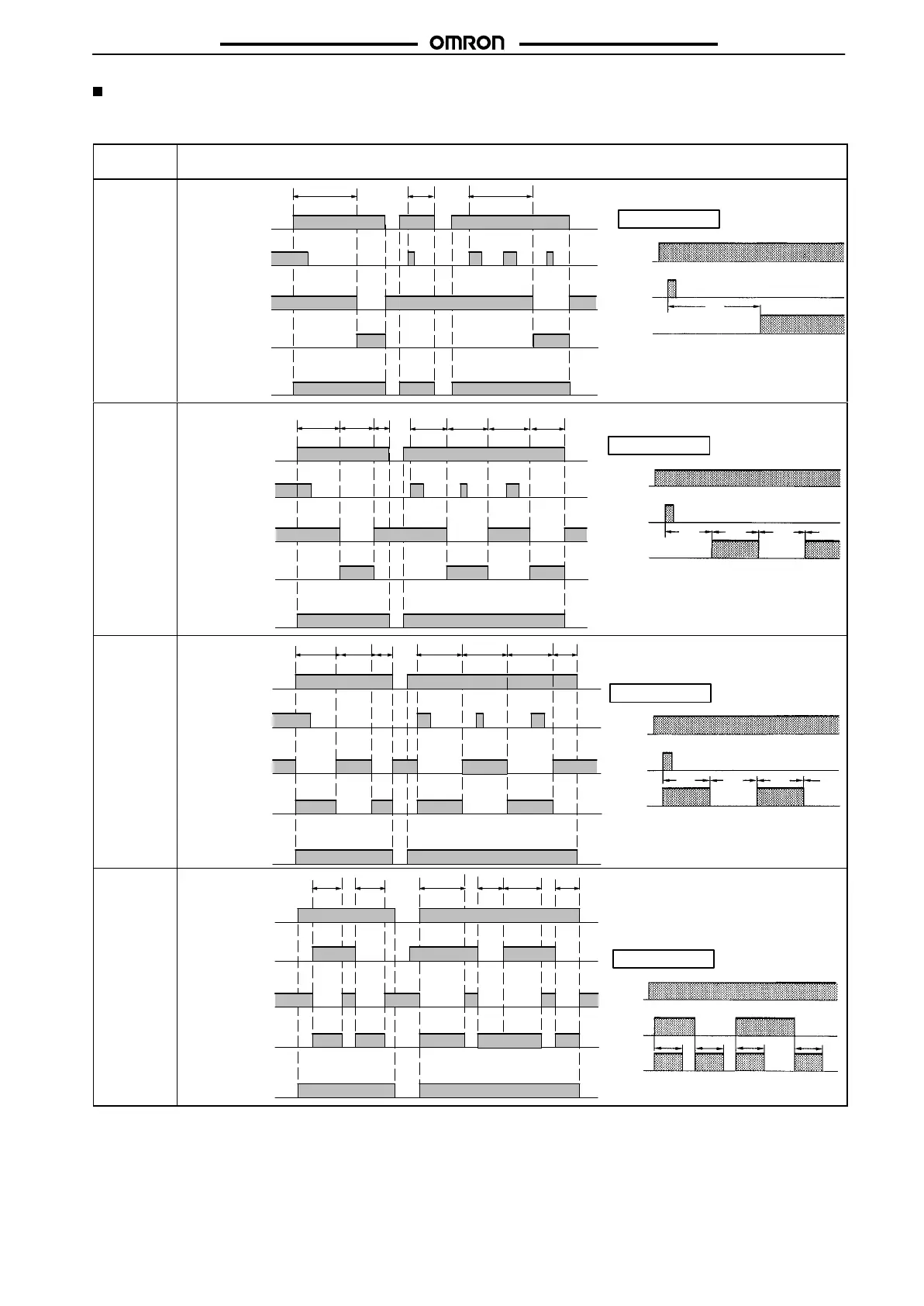
Timing Chart
Note: 1. The
minimum power reset time is 0.1 s and the minimum signal input time is 0.05 s.
2.
The letter “t” in the timing charts stands for the set time and “t–a” means that the period is less than the time set.
Operating
mode
T
iming chart
A: ON-delay
tt
Power (A
1
and A
2
)
Output relay: NC
15 and 16
Start (B
1
and A
2
)
(see note)
Output relay: NO
(output indicator)
15 and 18
t–a
Power indicator
Power
Start
Output
t
Basic
operation
* For power-on operation, impose voltage to the
Start input. The Timer starts operating at the
moment the power is turned on.
** Start input is invalid while the Timer is in opera-
tion.
*
**
B:
Flicker OFF
start
Basic operation
Power
Start
Output
t t t t
t t t–a t t t t–a
Power (A
1
and A
2
)
Start (B
1
and A
2
)
(see note)
Power indicator
* For power-on operation, impose voltage to the
Start input. The Timer starts operating at the
moment the power is turned on.
** Start input is invalid while the Timer is in opera-
tion.
Output relay: NC
15 and 16
Output relay: NO
(output indicator)
15 and 18
*
**
B2:
Flicker ON
start
Basic operation
Power
Start
Output
t
t
t t
Power (A
1
and A
2
)
Start (B
1
and A
2
)
(see note)
Power indicator
ttt t–a t t t–a
* For power-on operation, impose voltage to the
Start input. The Timer starts operating at the
moment the power is turned on.
** Start input is invalid while the Timer is in opera-
tion.
Output relay: NC
15 and 16
Output relay: NO
(output indicator)
15 and 18
*
**
C:
Signal
ON/OFF-
delay
Basic
operation
Power
Start
Output
tt
t
t
Power (A
1
and A
2
)
Start (B
1
and A
2
)
(see note)
Power indicator
t
t
t t t–a t–a
* Start input is invalid while the Timer is in opera-
tion.
Output relay: NC
15 and 16
Output relay: NO
(output indicator)
15 and 18
*
Note: The
start input of the H3DS-ML
j
model is activated by applying a voltage to B1 and A2 terminals.
The voltage can be applied by turning on the contact between B1 and A1 (Refer to
T
erminal Arrangement
).
 Loading...